Working ISS (01/23/2022)

This post is a bit of a quickie, but it covers an attempt to some of the basics about working ISS’ voice repeater and APRS digipeater. During this attempt to work ISS I wasn’t able to make any voice contacts, but I started with the following:

  • An Android phone running ISS Detector Pro
  • 5″ piece duct tape
  • Yaesu FT3DR
  • An Arrow handheld dual band 2m/70cm satellite antenna with built-in duplexer

Theory

As ISS or any satellite orbits earth in a non-geostationary orbit you’re likely to eventually have a certain number of passes over your location, depending on how the satellite is orbiting. You can use software to predict orbits, and therefore you can be ready when the satellite passes overhead. Ideally you’ll have the transponder frequencies of the satellite you’re trying to reach pre-programmed into your radio along with some doppler-shifted frequencies to try to reach the satellite as it approaches and departs. I didn’t do that, but have had decent luck without the doppler-shifted frequencies. Passes typically last minutes. What’s happening is that a lot of satellites have an uplink (ground -> space) and downlink (space-ground) frequency. Your radio must be able to transmit on one and listen to the other to make contacts. There are some cases where that’s not necessary such as working satellites with APRS digipeaters, or just receiving signals.

The attempt

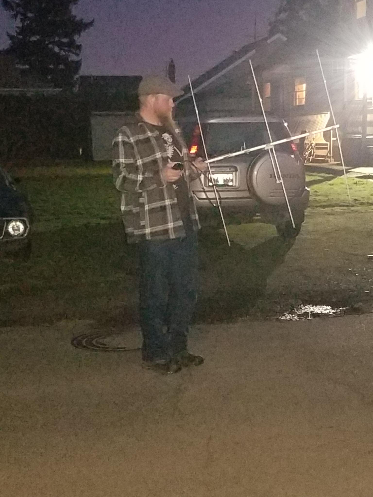
I used the ISS detector pro app to find a longer pass (this one was about 6 minutes long). Before the pass I set my antenna up, connected it to my radio, and made sure it was in working order. After that I taped the phone to the beam of the antenna between the first 2m elements where it would fit using a piece of duct tape folded in on itself. Taping the phone to the boom enables me to aim the antenna using the app (screenshot later). I also configured the frequencies for the APRS digipeater on ISS, the crew communication uplink and downlink frequencies, and the FM repeater frequencies. As a side note sometimes astronauts, who are also licensed ham radio operators, will man the radios and talk with folks on the ground. In addition to programming frequencies you need to also program your APRS radio to use the digipeater path ARISS, otherwise the digipeater won’t send your packets back down to other stations.
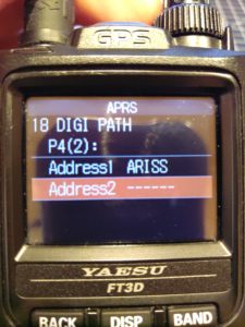
Yaesu FT3D radio's APRS path configured to be "ARISS".
Yaesu FT3DR digi path set to ARISS or ISS.

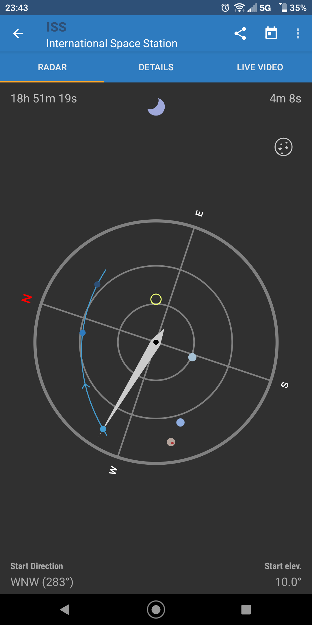
Now it’s time for action! There’s a very narrow window to hit the ISS, so there’s a need to be quick and prepared. I went out in the street near my house a few minutes early with a clear-ish view of the sky and aimed the antenna at the satellite using the app. A screenshot below shows what the aiming screen looks like. The yellow circle is the direction the top of your phone is pointing and that should be aligned with the satellite on its track, the blue line with dots. The center of the screen is up and the and the outer ring is down. As the satellite passed I just aimed the antenna with the aid of the phone and tried to use the repeater. I didn’t hear anyone, but was able to switch to APRS and sent a beacon. I saw that the packet I sent was digipeated by ISS! Following that I checked the ARISS page and saw my call sign! You can also check https://aprs.fi and see your location as well as the path by which your packet arrived. The first hop for my position report was the ISS.
aprs.fi screenshot showing a path via NA1SS
An aprs.fi screenshot showing a path digipeated by NA1SS before going to APRS-IS via KM6YLW-2.
Camping in the Tillamook State Forest (1/21-23/2022)

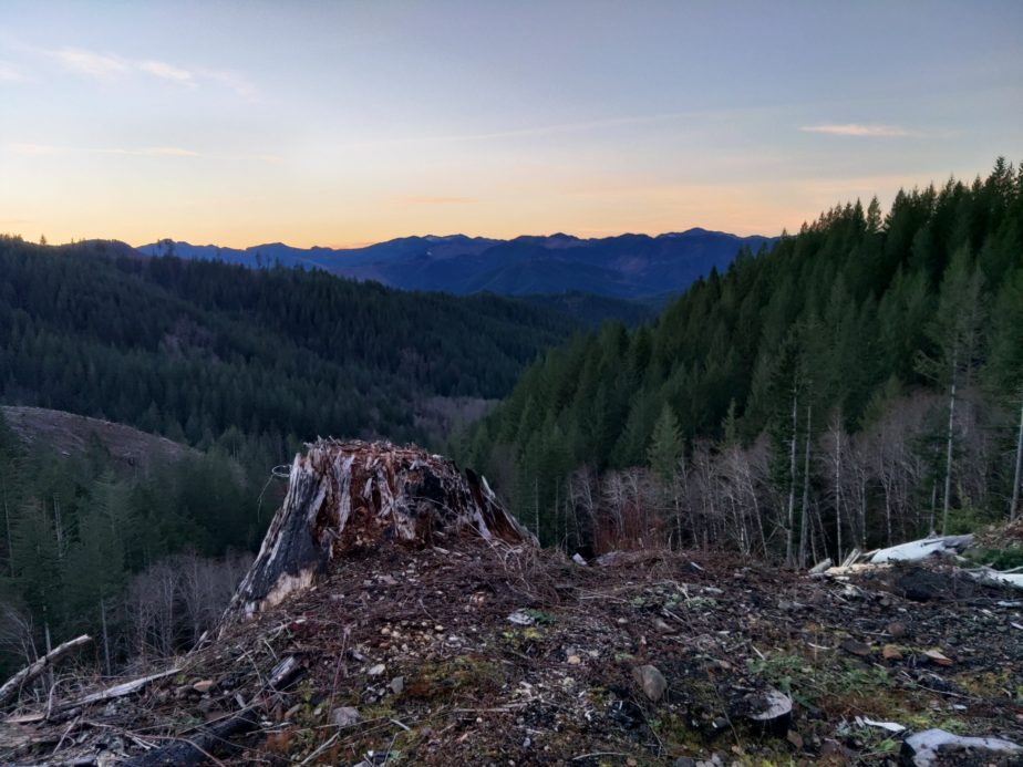
It’s been a while and this will be a big post! My partner and I were able to go camping over the weekend, and if you’ve read any of my blog posts you won’t be surprised that I took the opportunity to practice some comms and off grid operating. I wanted to work HF, do some shortwave listening, and see if I could do any UHF/VHF communications. Additionally I wanted to run off of the 100AH battery box for a couple days to see how well it held up under constant use. This is also the first camping trip I brought the speaker stand antenna mast setup on.

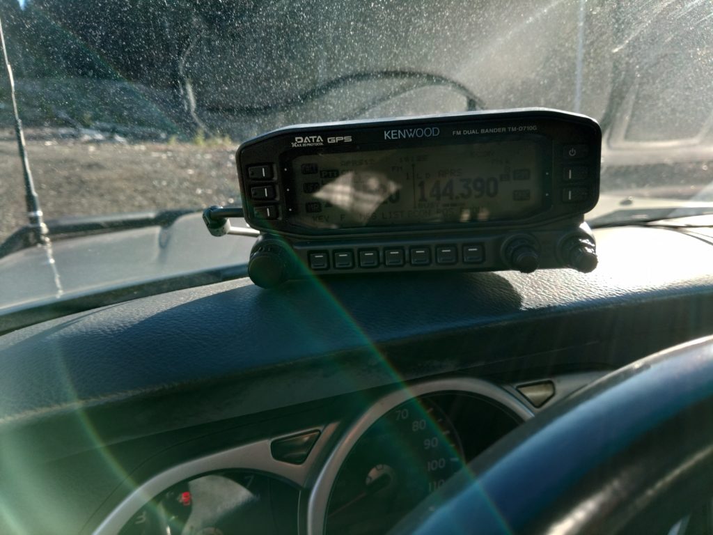
On the way out I ran APRS with the Kenwood TM-D710G and the COMET-NCG CA-2X4SR antenna that mounts on the hood of the 4Runner. I noticed that on the way out that I had APRS coverage nearly the whole way out.

The first night we arrived late so I did a bit of SWL. I mostly got Radio Havana Cuba, Radio Nikkei, a distant station broadcasting in Mandarin, and Radio New Zealand International.

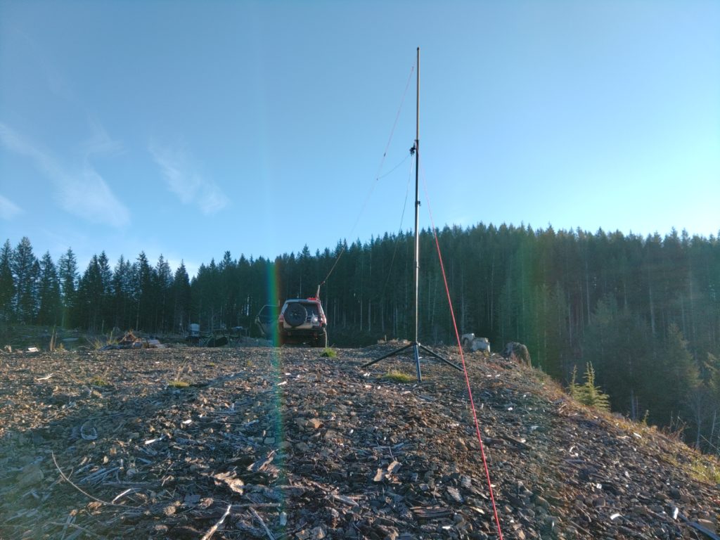
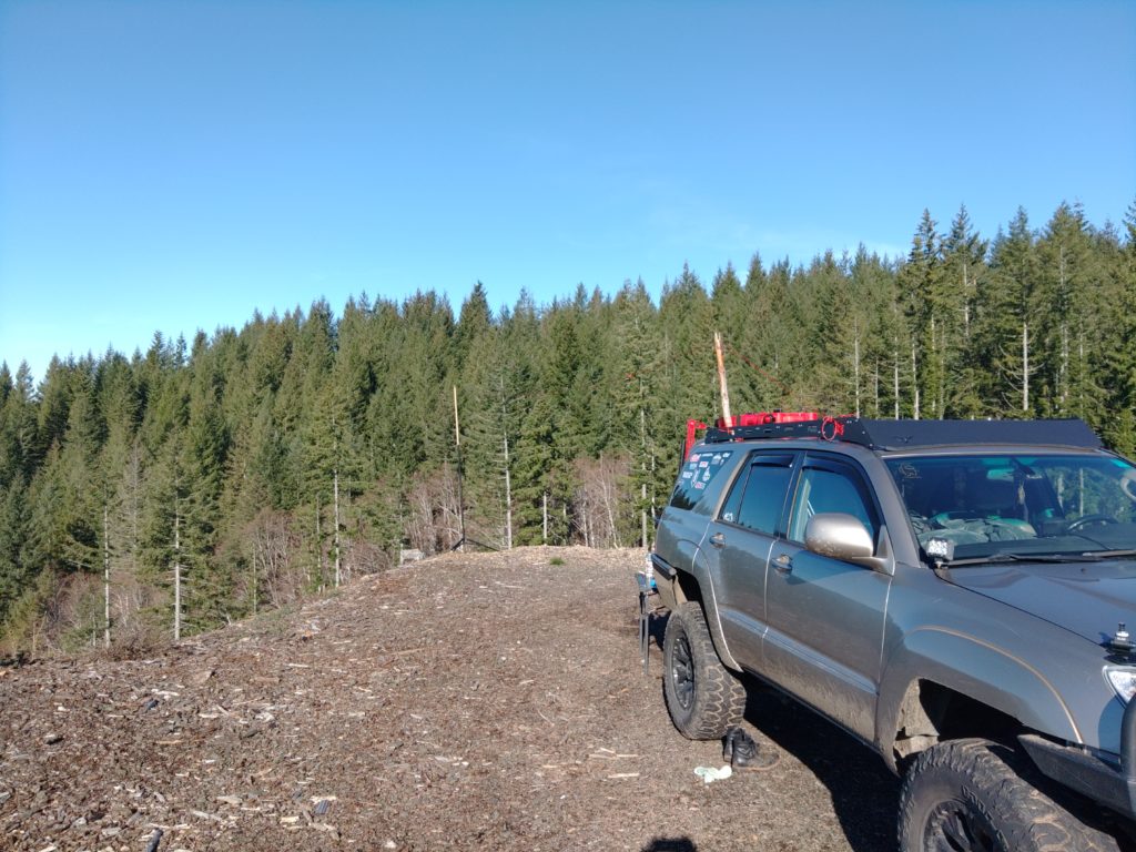
The next day I set the antenna up following a fun walk in the woods below the camp site. Most of my work on HF was done using the usual Endfedz Trail friendly 10/20/40m antenna. I strung it between the 4Runner and my portable antenna mast. I also added a 6m end fed dipole to the setup to see if I could reach Kevin, K7AJK from my camp site on the Lab599 TX-500. We had no luck. I wasn’t actually able to make any voice contacts on 20m with this setup even running at 10W, but there was a contest on the band so it was both congested and I suspect folks were running at fairly high power levels to make contacts. As you’ll be able to see from photographs I did a little hack with a stick I found to push the antenna higher off the ground on the truck side. It was especially helpful in preventing the hatch back from striking the antenna.

View of an antenna mast guyed to the ground and a line with an antenna running to a SUV in the background
Guyed antenna mast with two antennas added
View of an SUV with a piece of wood lashed to the roof rack holding some paracord off of the top of the vehicle.
Found piece of wood used to push the antenna higher off of the roof of the 4Runner
An antenna tied to paracord running from the upper-right corner of the photo to a mast several feet away on the edge of a hill. The transformer for the antenna is visible with feed line hanging down. Forest in the background.
The Trail Friendly Endfedz is strung along some paracord to prevent damage to the antenna if the mast blew over.

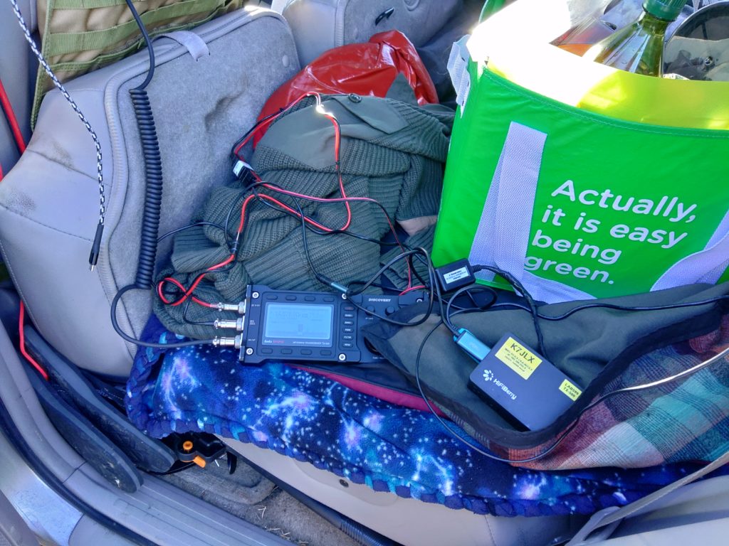
After a few hours of having no success running phone I decided to switch to packet. Moving the radio into the vehicle reduced the SWR and allowed me to run the entire setup from the 100AH battery since I had used the 4.5AH battery quite a bit for SWL already. I had also been simultaneously been running my 2m rig and APRSDroid on the tablet connected via Bluetooth to the mobile radio with a Mobilinkd TNC3+. I was able to send a number of text messages back and forth between friends using SMSGTE, which was nice given the complete lack of cell service. At this point I was still using the antenna on the truck.

A Raspberry Pi connected with a Lab599 TX-500 radio via two cables sitting in the back of a 4Runner.
Lab599 TX-500 connected to the off grid Raspberry Pi
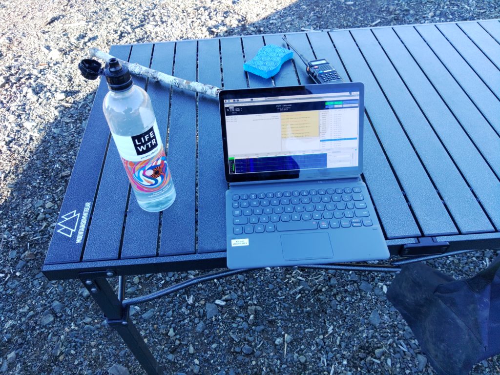
A tablet sitting on a metal camping table running the JS8Call application.
Tablet running JS8Call
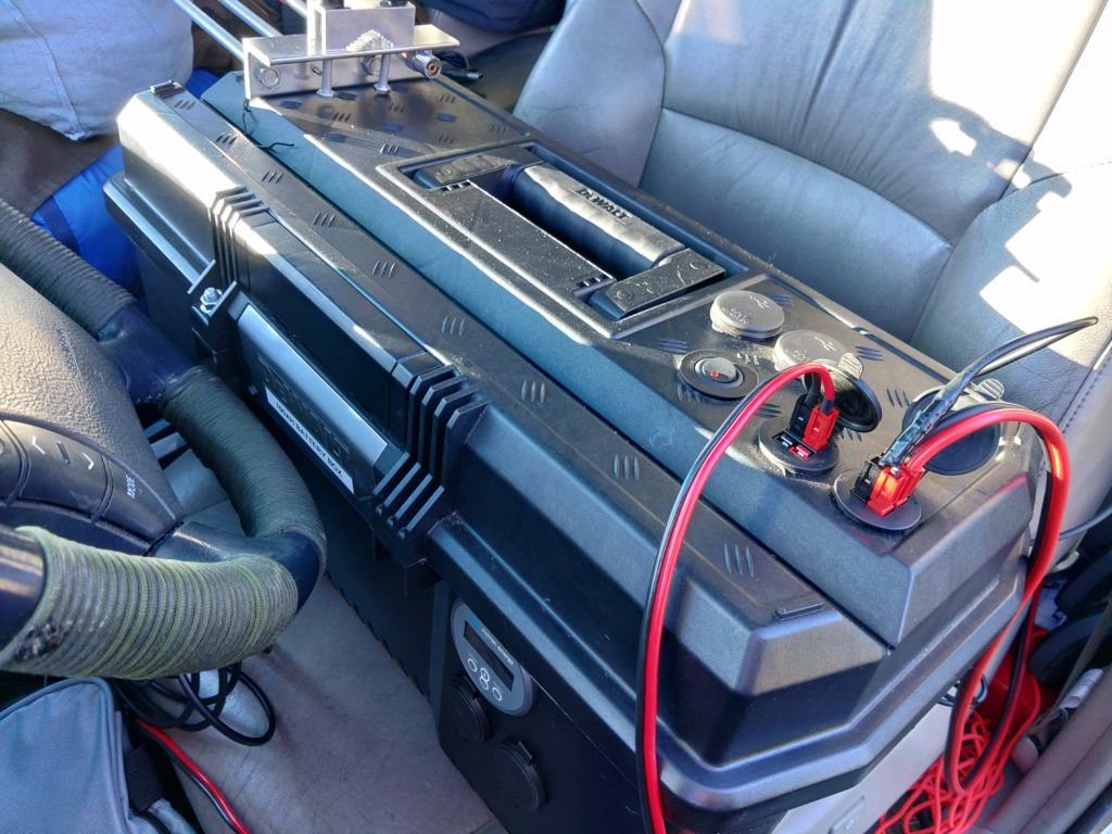
A toolbox with power connections running from it sitting in the front seat of a vehicle.
100AH battery box connected to the Kenwood TM-D710GA in the vehicle, the Lab599 TX-500, and some lighting.

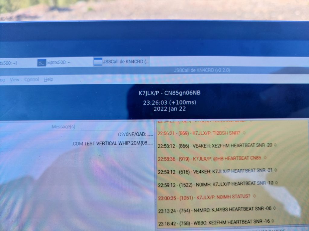
After quite some time operating on digital I decided to test some configuration changes I made to js8cli to increase the accuracy of maidenhead coordinates I was submitting to APRS-IS via Internet-connected stations running JS8Call. I had some pretty good luck as my position was accurately reported.

A photograph of the screen of a tablet showing the JS8Call application running. A callsign, timestamp, and 10-digit maidenhead coordinate are displayed prominently in the photo along with a screen showing contacts with other stations.
JS8Call screen shot showing a 5-level maidenhead position set via js8cli running an daemon mode
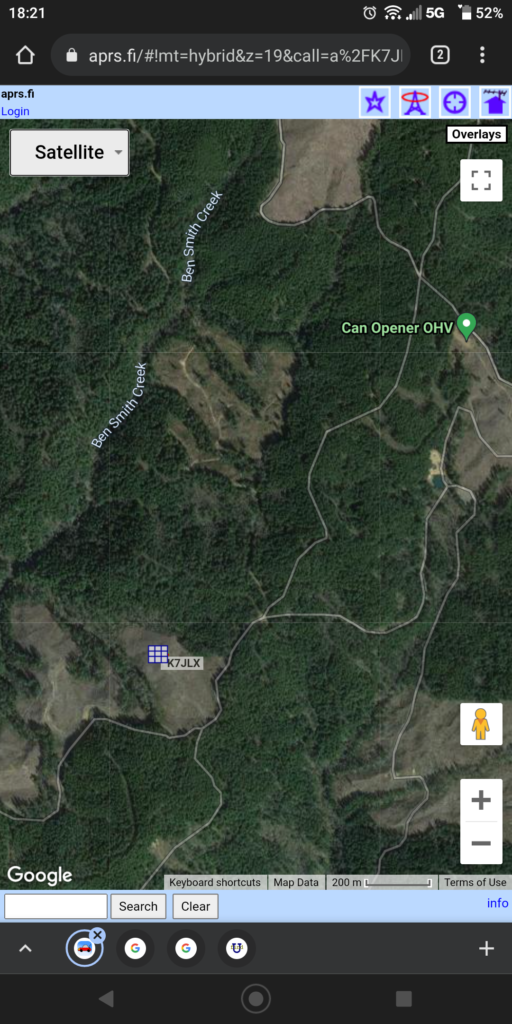
A screenshot of the website aprs.fi showing a Google satellite map with a rectangular marker for K7JLX placed in a clearing.
My position as displayed on aprs.fi

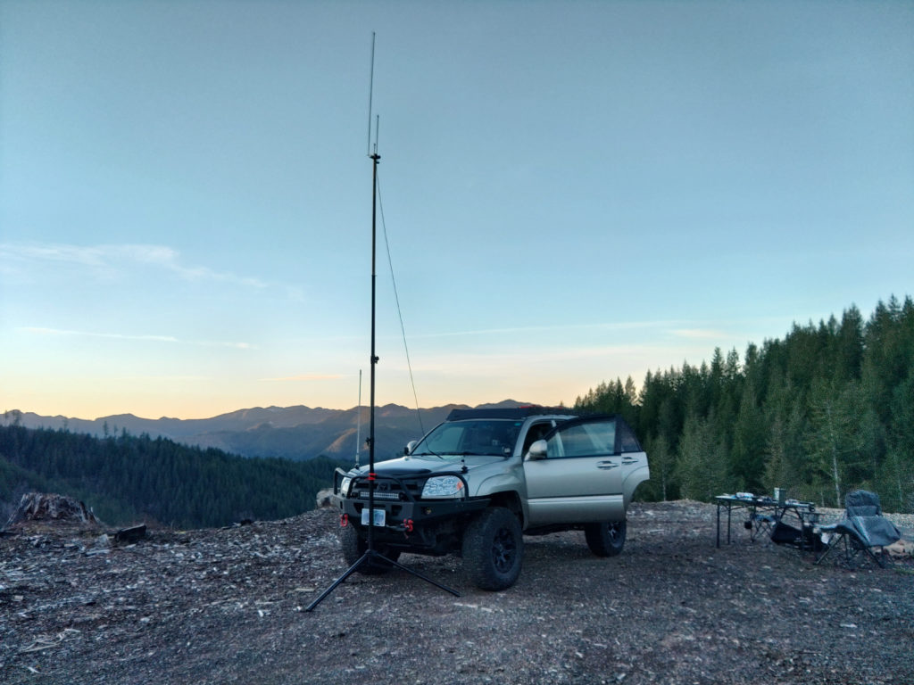
Apart from all the fun I had on HF, and walking around the forest with my HT (where I was reliably digipeated at 5w) I also figured I’d try to see if I could hit some of the repeaters in the Portland area, so I swapped the vertical antenna on the vehicle for my collapsable J-pole and speaker stand antenna mast. Much to my surprise I was actually able to get into the repeaters in the Portland area at 5w, but it was a bit sketchy as sometimes they wouldn’t key up. Apart form that I could get a bunch of APRS stations and digipeaters as well as some folks on the 2m calling frequency. I actually ended up having much better luck on 2m than on HF this time around.

The head unit of a Kenwood TM-D710GA radio placed on the dash of a vehicle.
Kenwood TM-D710GA on the dash of the 4Runner
A 4Runner with an antenna mast tied to the front bumper and connected to the vehicle with feedline. There's a camping table and chairs to one side and in the background are trees, a valley and a mountain on the other side of the valley.
The 4Runner antenna hood antenna swapped for an elevated J-Pole on the speaker stand mast.
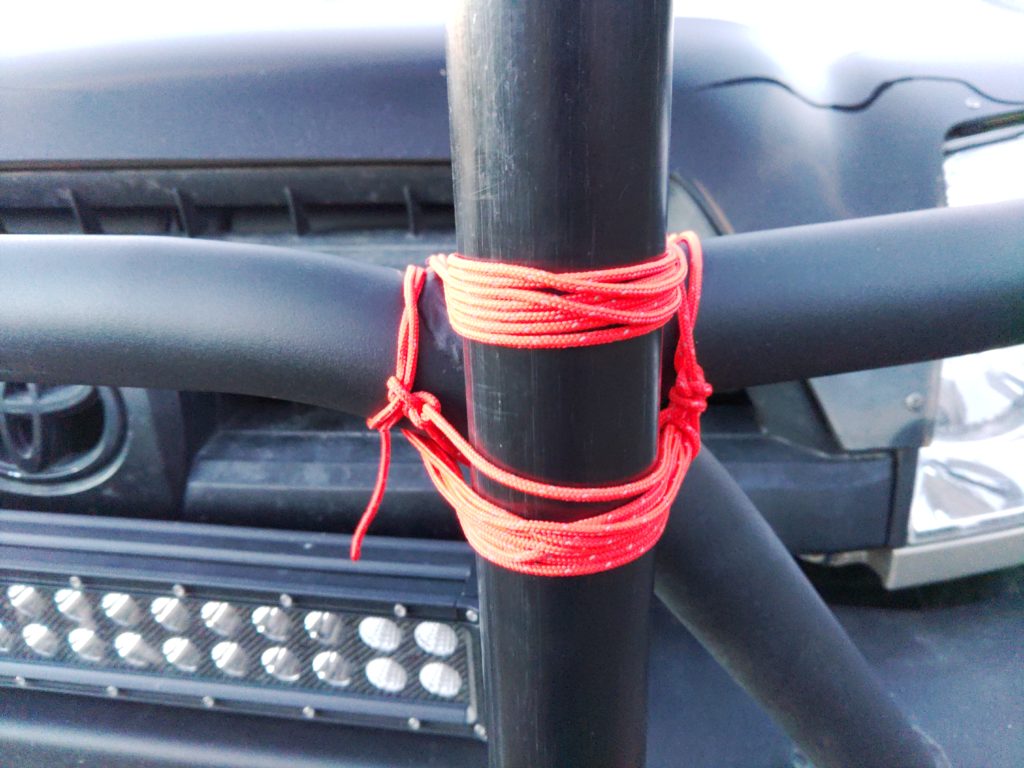
Close-up of paracord tying the the antenna mast to steel tubing on an offroading bumper.
Using paracord to lash the antenna to the bumper of the truck

As you might have noticed from the pictures above I ended up moving the antenna because winds were getting higher and I was afraid the antenna might move side-to-side on the bumper’s tubing. I ended up shifting it toward the driver’s side where I could secure it to both the tube running horizontally and to the spot where the tube split, meaning the mast wouldn’t shift from side to size because it was secured with the paracord on both axes. since the antenna mount on the vehicle uses the same connector as most of my coax and the J-pole I was able to just connect the J-pole directly to the existing cabling in the 4Runner. Easy!

For the entire trip apart from doing some SWL with the TX-599 on its 4.5AH battery away from the truck and by the fire ring I ran all the lighting and radios from the 100AH battery box. We charged the tablet, my partner’s phone, and my phone from the battery box as well. We only drew down to 96% in two days. One day had a lot of heavy radio usage as well so that’s all a good sign.


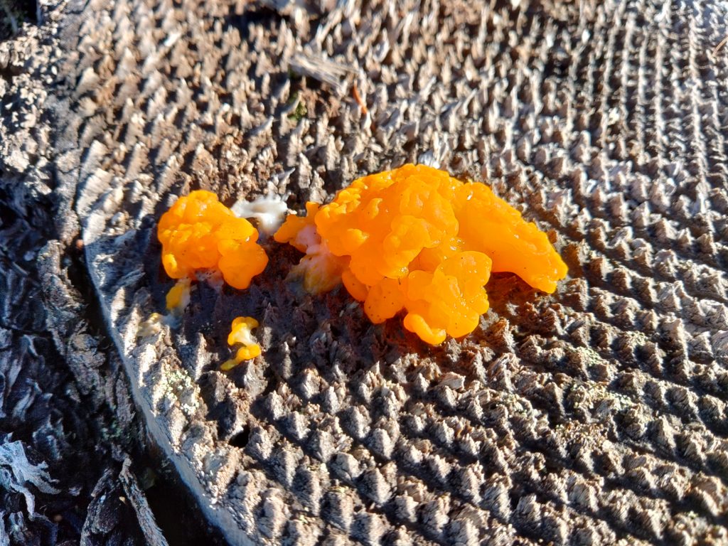
Yellow witch's butter growing from the top of a tree stump with diamond cut patterns.

Some witch’s butter we found on a stump near our camp site

Operating while camping on Mt. Hood 7/31/2021

Hello all, it’s about time I wrote a post about my camping trip my partner and I took a couple weeks ago. I took my trusty Lab599 TX-500 kit, a couple 20W GoalZero Nomad solar panels, headset, and table/chair combo up camping with our “new” 4×4. I wanted to do some HF QRP and some handheld UHF/VHF operation while I was out. I brought some of the same portable furniture that I used at the beach last post since it worked out so well.

The view was pretty sweet for this one. The smoke from the wildfires made everything a bit more hazy but pretty great none-the-less.

View of a heavily forested valley from a high vantage point. In the foreground a radio is sitting on a gray metal camping table.
View while operating

While operating HF I made a number of contacts, and the solar panels kept the 4.5Ah Bioenno LiFePO4 battery built into the HF QRP radio kit charged the whole day. The first HF contact I made was with Stefan, AF6SA who was working POTA in Eldorado Natoinal Forest (K-4455). His signal was 5/6 on at about 450 miles away on 20m. I also made a contact with VA3AAA, Stanley in Ontario, Canada. I was pretty excited to reach Ontario with a low power radio. That contact was also logged on 20m. I also made a contact with the K0GQ radio club in MO on 20m. All of these contacts were made between 5 and 10w using the Trail-friendly EndFedz EFT-10/20/40 antenna strung between a couple trees about 50′ apart and about 25′ above the ground.

I switched radios and bands to see if I could get into some of the repeaters in the Portland area (I could) with my Yaesu FT3DR and a Signal Stick antenna. I ended up on 2m and caught two hams on 146.520Mhz doing a SOTA activation: K7AHR and K7IW. I think they were on Lookout Mountain, but I can’t remember and didn’t properly log it. I was running 5W for those contacts.

Tour of the radio setup at the camp site

Modified Ed Fong roll-up dual band J-pole antenna kit

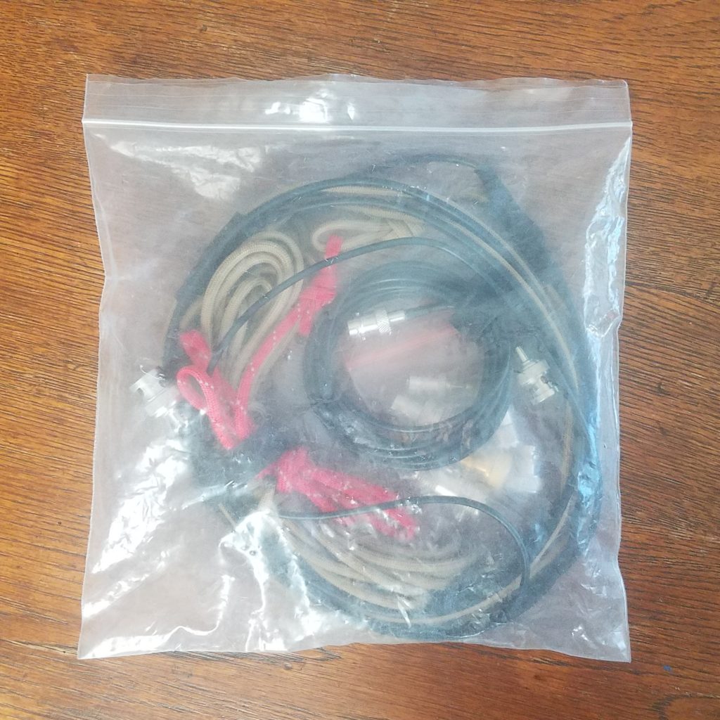
Plastic bag containing a roll-up J-pole antenna and various adapters
Ed Fong roll-up J-pole kit

Howdy y’all! This is my second post for today. I wanted to explain my modified Ed Fong roll-up J-pole antenna and kit. This is the stock Ed Fong DBJ-2 (ham) dual band roll up antenna kit with a twist and an extended adapter pack. The antenna itself is pretty great, but I noticed while using it that there were a couple issues regarding setup. I had trouble hanging it in bushes and trees without carrying some extra materials like paracord. In addition to that sometimes the antenna would snag and you’d need to pull on the attached feed line to get it down which could damage the antenna by weakening connections between the feed line and ladder line or separating them entirely! The antenna comes with a wire tie attached to the end which could be used to hang it from a small object, but it didn’t work well because unless you were hanging it from a small metal object like a nail. Using a J-pole with metal objects near them and above the bottom of the antenna can detune them, and likely increasing the the SWR of your setup. Here’s how I solved both of those problems and set the kit up for a number of radios I and other friends have just in case we needed to hook something different up to it. It has come in handy already.

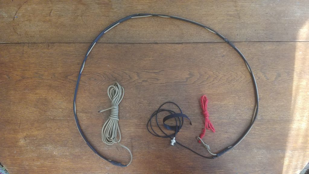
Unrolled j-pole antenna on a wooden table
Unrolled J-pole antenna

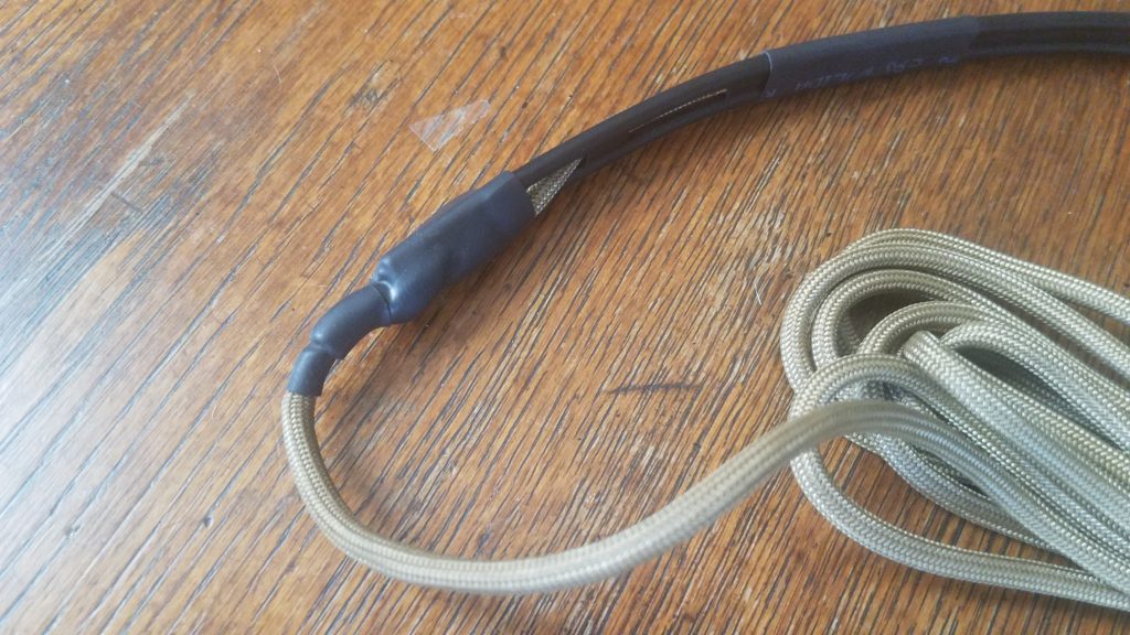
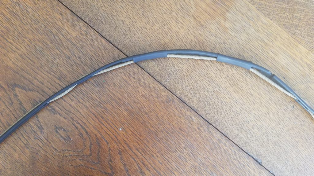
Solving the ease-of-hanging and snagging issues turned out to be the same solution – creative use of inexpensive paracord and heat shrink tubing. The ladder line that serves as the antenna’s radiator has convenient slots that one can weave paracord through. If you tie the paracord to the top of the antenna and weave the paracord through the slots in the antenna you can take a long end and throw it over a branch or tie it to some overhead structure, and also use it as a more rugged line to pull a stuck antenna down with. My initial setup didn’t have enough paracord on the bottom to pull the antenna down when it was up higher and stuck so I added the bright red line to give it more length to retrieve it from a higher location. The bright red length of paracord with a reflective 3M strip woven in also makes it more visible in low light or when you’re looking for the end with a flash light. We can now hang and retrieve our antenna easily and prevent damage to it if there’s a snag you need to apply more pulling force. Here are some more detailed pictures of how the paracord is tied on, woven, and secured by heat shrink tubing.

paracord tied to the antenna with the knot covered by heat shring tubing.
Paracord tied to the top of the antenna and the knot is covered by heat shrink tubing
View of the paracord woven through the antenna and secured by intermittently placed pieces of heat shrink tubing.
Paracord woven through the antenna and intermittently secured by heat shrink tubing
The bottom of the antenna secured with heat shrink tubing and the two sections of the recovery end are tied together

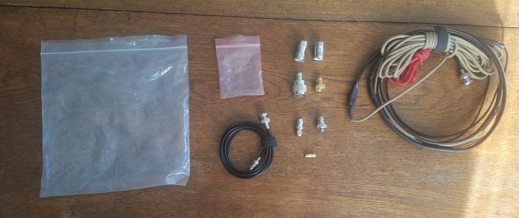
At this point we should probably talk abut the kit in its entirety. The modified antenna is obviously a critical component, but being able to connect the antenna to various radios is also very important. For that we’ll start with an exploded view of the kit.

Plastic bags, cables, adapters, and the cable arranged on a wooden table.
All components of the kit arranged on the table

This kit isn’t anything really fancy. It comes with the stock antenna and male-to-female extended BNC cable. The antenna itself has a BNC end, but not every radio has a BNC connector. I’ve used this antenna with a number of radios including dual-band Kenwood mobile radios, a Baofeng UV-5R, a Yaesu FT3DR, and a Yaesu FT-857D. The two of those radios have a PL-239/SO-239 connector, one has a male SMA, and one has a female SMA connection. This adapter kit allows an operator to connect any radio with a BNC, SMA male, SMA female, or a PL-239/SO-239 connector to the antenna… additionally you can connect one or more pieces of coax with PL-239/SO-239 cables as well. This can be handy if the antenna is up high or if the radio is far from the antenna. Here’s a list of the parts in the graphic top to bottom, left to right:

  • Medium sized heavy plastic zip-loc bag to hold the kit
  • Small heavy plastic zip-loc bag to hold small adapter parts
  • 6′ BNC male to female extension cable (originally came with the antenna)
  • 2x PL-239/SO-239 barrel connectors for both “changing the gender” (I’m not a fan of this terminology, but it’s what’s used broadly) of the BNC to PL-239/SO-239 adapter and for connecting two pieces of feed line together.
  • BNC to PL-239/SO-239 adapter
  • BNC to SMA male adapter with a wide-flanged connector (for my Yaesu HT)
  • BNC to SMA male adapter with a narrow spinning connector
  • BNC to SMA female adapter with a wide-flanged connector
  • BNC female barrel connector for use with the narrow spinning connector to adapt it to a male port
  • Rolled up J-pole antenna

With this set of adapters and cables we can connect this antenna to a wide variety of radios which might be handy in an emergency, or if you happen to forget another antenna. It’s also worth mentioning that this method could also be applied to other roll-up J-pole antennas, not just for ham bands.

Cold weather backpack setup test

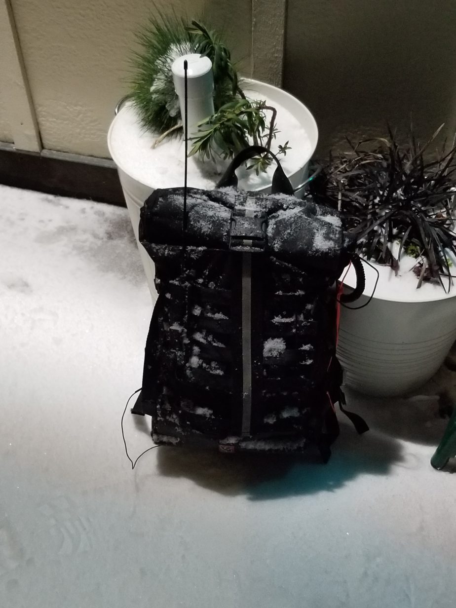
So, the weather in Portland has been pretty snowy which is a touch unusual! As most folks have been inside and not out attempting to drive on icy and snowy roads which are not plowed I decided I’d take my HT for a walk in the cold weather and test methods of keeping it warm enough to not have the battery fail as the temperature is dropping to ~18F with wind chill. My partner and I have been walking to the grocery store and taking our dog out so I decided to test an external antenna I’d built to mount on my backpack a year ago in the gnarly weather. I did some tests with APRS and some 5w FM phone as well. The theory here is that keeping the HT inside the fairly sealed bag would preserve some amount of air that’s warmer than the bag’s surroundings. It seemed to work as I was out with this setup for a few hours at a time and battery performance was within expectations.

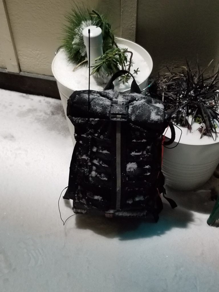
Snow and ice covered backpack set on a snow-covered sidewalk with counterpoise extending down and antenna extending up.
Setup covered in ice and snow.

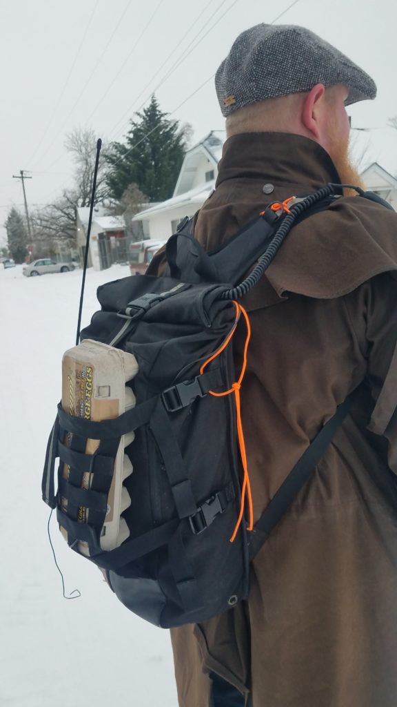
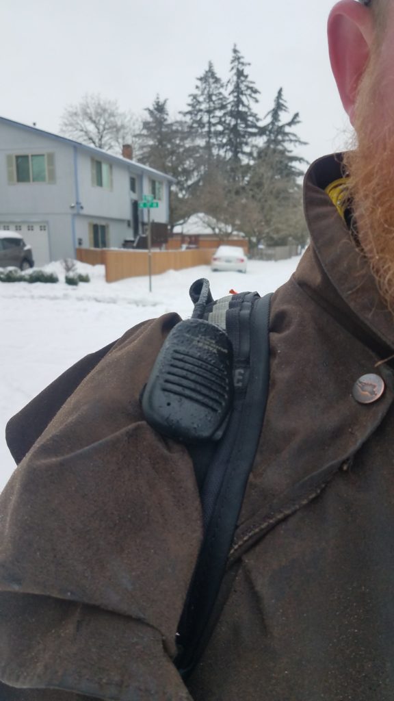
In order to not go stir crazy I’ve been taking walks with my partner and we’re close enough to a grocery store to just walk and pack our food in our bags which is very fortunate. I’ve taken the opportunity to test different ways of carrying the HT so it doesn’t get too cold, and to test a MOLLE antenna holder with a simple antenna and counterpoise setup. During the grocery store run pictured below I was able to reach stations in SE and NE Portland with a strong signal. I was between 2 and 9 S units into a station in Battelground, WA as well depending on structures around me. The antenna I’m using in this picture is a Nagoya NA-771. I used that instead of my Signal Stick because the signal stick doesn’t stay rigid in cold temperatures and will curve and lay over giving poorer performance. The speaker mic was used as both a speaker that I could hear outside the bag and as a sacrificial component in the event something gets too wet. A $30 speaker mic is much cheaper than a new HT. I did test the SWR on this setup and 2m performed very well near 1.2, but 70cm performance was poor with the SWR being near 2.8.

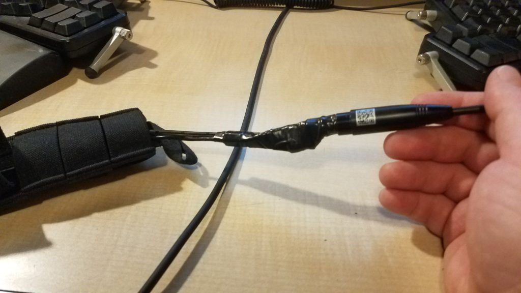
The small bit of orange paracord is used to secure the speaker mic for cable routing purposes. When the mic comes un-clipped intentionally or on accident this cord makes it easier to grab and replace or remove and use. The longer orange paracord holds the weight of the HT in side the bag so the antenna cable and speaker mic don’t hold it up. It’s also necessary to hold it up in the bag to make sure there’s enough speaker mic cable to reach outside the bag and to my shoulder.

HT in the bag suspended by paracord.

The HT holder inside the bag is suspended by the longer bit of paracord that runs through a loop on the HT holder. This suspension system also makes it easy to load the bottom of the bag with heavier items that might otherwise crush the HT or damage connectors.

The above gallery shows the antenna assembly set up but not mounted to the webbing on the backpack.

A successful-ish EMCOMM test deployment

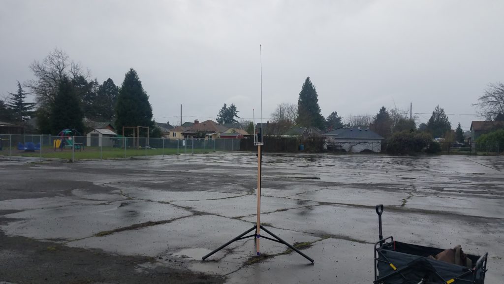
Howdy everyone! I wanted to tell the tale of a short walk with a wagon in the rain followed by some radio tests. I decided I’d like to test moving to my staging area during a disaster response scenario. My goals were to test making contacts with my Yaesu FT3DR and do voice as well as Winlink with my Kenwood TM-V71 and portable Winlink setup. This will also be the first deployment of my Arrow OSJ 146/440 open stub dipole. This model has the split 2m element for easier transport.

Cloth-sided wagon containing various equipment and a backpack leaning against the side.
Wagon with the antenna, mast, and a couple folding chairs. Also pictured is my water resistant backpack with the radio gear and feedline.
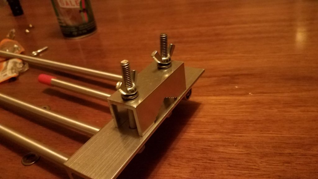
Wing nuts installed on the antenna's pipe clamp.
Slightly modified Arrow OSJ 148/440. I replaced the stock hex nuts with 1/4″ 20 wing nuts to remove the requirement for a wrench to install the antenna in the field.

After arriving at my deployment site I removed the 1 5/8″ closet rod from the inside of the speaker stand. The long end of the closet rod stays inside the speaker stand tubing for easy transport. The stop for the closet rod is made from three eye screws that double as guy line connection points. The three eye screws are installed just above the top band of purple duct tape (reduces vibration and motion when the closet rod is installed in the end of the speaker stand).

J-pole mounted to a wooden closet rod resting against a speaker stand. The split 2m element is affixed for transport.
J-Pole with the second half of the 2m radiator threaded in place for transport.

The next step is to install the top portion of the open stub J-Pole.

J-pole mounted to a wooden closet rod resting against a speaker stand. The split 2m element is installed for transmission.
Open Stub J-pole atached to closet rod resting against the speaker stand with the 2m element fully assembled.

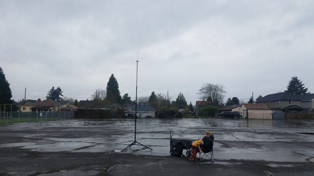
After the feedline is attached to the J-pole the closet rod with the antenna attached is installed in the speaker stand with the tape end of the closet rod in the top of the speaker stand. The closet rod is resting on the three eye screws that prevent it from slipping down inside the speaker stand tubing. The two telescoping sections of the speaker stand are fully extended and the locking pins are in place.

Fully extended speaker stand with closet rod and antenna attached. The wagon, my partner, and our dog are off to the side.
Antenna fully extended. Also present is my partner and our dog for moral support.
A picure of the feedline velcroed right above the tripod component of the speaker stand.
A velcro wire tie is used to anchor the feedline to the bottom of the antenna mast to prevent it from being pulled over from the top if someone trips on the cable.
Yaesu FT3DR connected to the feedline with the wagon and antenna stand in the background.
My Yaesu FT3DR attached to the feedline with a SMA to PL-259 pigtail.

I was able to make a couple contacts using the Yaesu HT at 5w and monitored APRS transmissions for a while. So far everything is good.

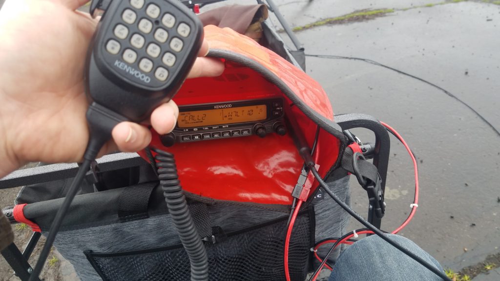
Hand holding microphone of Kenwood TM-V71. In the background the radio is in a dry bag and sitting on the wagon.
Kenwood TM-V71 connected to the feedline and battery in the backpack. It’s protected from rain by an Ortleib dry bag.

The Yaesu HT is stowed in its bag and the Kenwood mobile radio is connected to battery power and the feedline. It’s also protected from the rain by a 5L Ortleib dry bag. More contacts are made on 2m without issue. I was able to make contacts in Portland, OR, Aloa, OR, Washugal, WA, and Vancouver, WA at 5w. More good news!

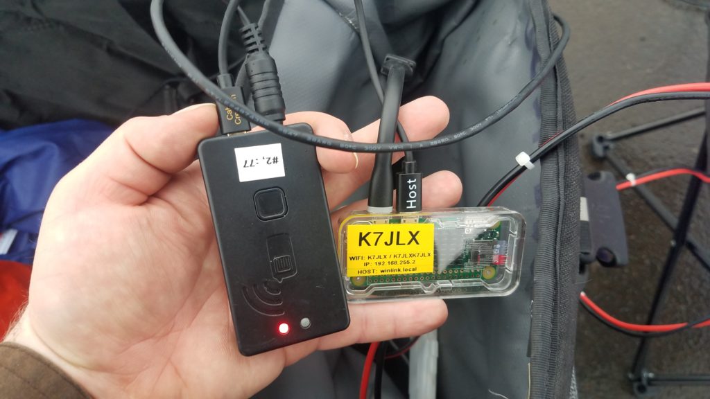
Hand holding the Mobinlinkd TNC3 and Raspberry Pi Zero W connected to each other. Radio data connector is also set up.
Winlink host, TNC, and radio connected.

It was finally time to send and receive some e-mail! I connected the Winlink Raspbery Pi to the power supply and the Mobilinkd TNC3 to the data port on the TM-V71. I pulled my phone up, found the generated wireless network, joined it…. and nothing! It partially connects but doesn’t get an IP address. Strange, but no matter. I assigned a manual IP to my phone and tried to connect to the Pi via IP address. The connection still failed. I rebooted the Pi and tried again. The wifi network shows up, I join it, no DHCP IP address. Bummer! All my tests having either been complete or failed it was time to pack up and head home.

At home I boot the Pi and it joins the home wifi network with no issue. I SSH into the Pi and begin reviewing the configuration for Dnsmasq (DHCP/DNS server). Everything looks good and the configuration is valid. I then look at the autohotspot script. It has the default IP address that the script ships with set. Then the “aha!” moment strikes. As part of writing my Winlink host setup guide I re-ran the Autohotspot install script so I could make sure my documentation was right. The fix is now obvious: I just changed the IP address in the Autohotspot script, kicked the Winlink host off my wifi network and restarted it. I’m now able to connect, get an IP address, and connect to Winlink and the documentation server!

Lesson learned… always re-test your setup after you mess with it, and if you re-run a setup script you should verify that your setup runs properly afterward. Fortunately this was not a emergency deployment and was close to my QTH.

Other things I learned from today:

  • The wagon doesn’t negotiate steep curbs well without a bit of finesse.
  • The antenna mast should be lashed in place on the wagon during transport so it doesn’t move in the wagon.
  • The wing nuts on the J-pole can get over-tightened easily making it hard to dismantle the setup.
  • The allthread stub that connects the two parts of the 2m element on the J-pole can be unscrewed easily and lost when the element is being removed. I’ve dropped it 3 times in the first 48 hours of having the antenna. Some red or blue Loctite is probably a good idea to keep the end of the stub fixed in the removable portion of the 2m element. The red (permanent) Loctite will also keep moisture out of that joint.
  • Sometimes the telescoping tubes on the speaker stand stick.
  • I live in NW Oregon and figuring out a wind and rain shelter is probably a good idea.
  • The speaker stand is pretty stable and sturdy. It will probably work without guying in mild wind.