This won’t really be a post about doing a lot of operating. It’s mostly about powering and recharging stuff. The long story short of operating from the specific site we were at is that I didn’t make any contacts apart from another station on JS8Call that heard one of my heartbeats. I wasn’t in a good position to be heard, but I could hear a lot of other stations on 40m throughout the afternoon and evening. I was also able to hear Radio Havana and what I suspect might have been Zambia NBC Radio 1 for a few minutes.
I was able to recharge the Bioenno 4.5Ah battery in an hour or so as we broke camp and packed the vehicle. I’d been using that radio the previous day and listening to shortwave stations the whole night. A solid hour of charging at 1.1A using the BuddiPole PowerMini on a single GoalZero Nomad 20 solar panel was enough to replentish the battery.
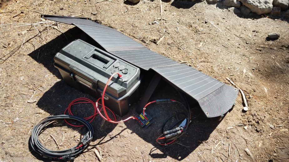
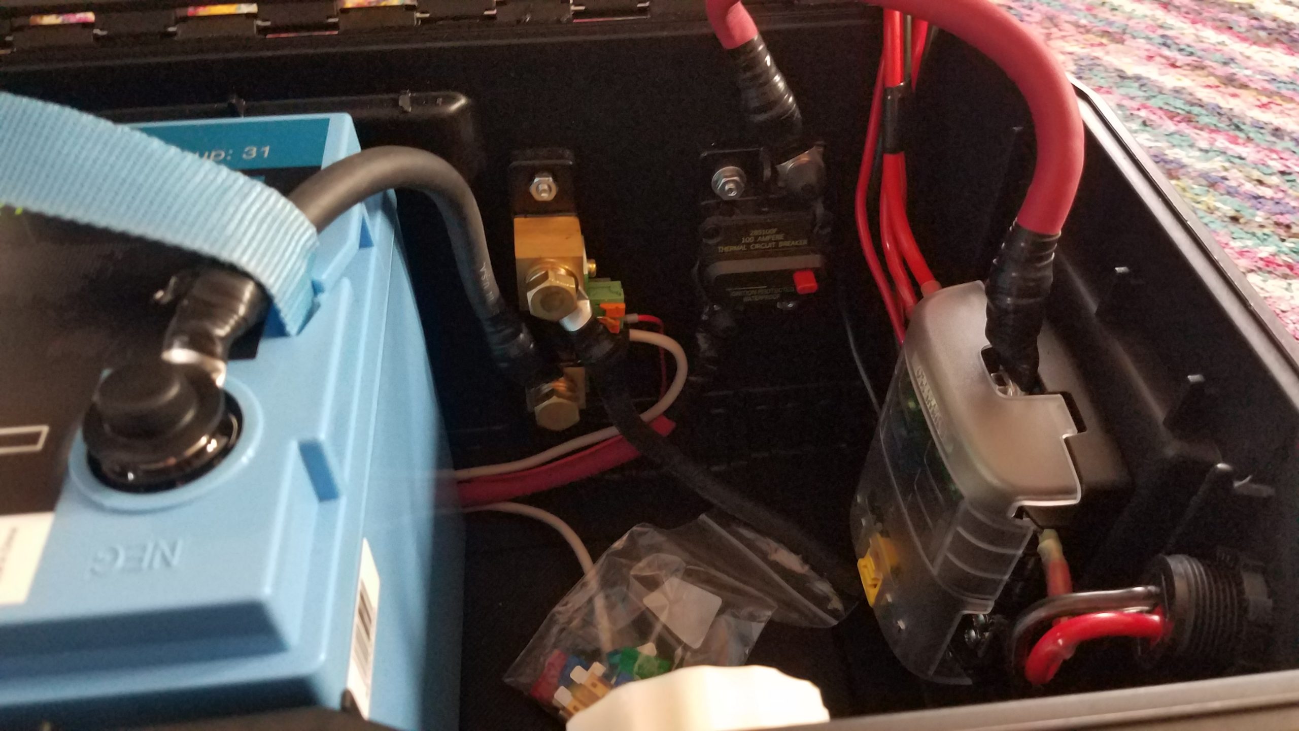
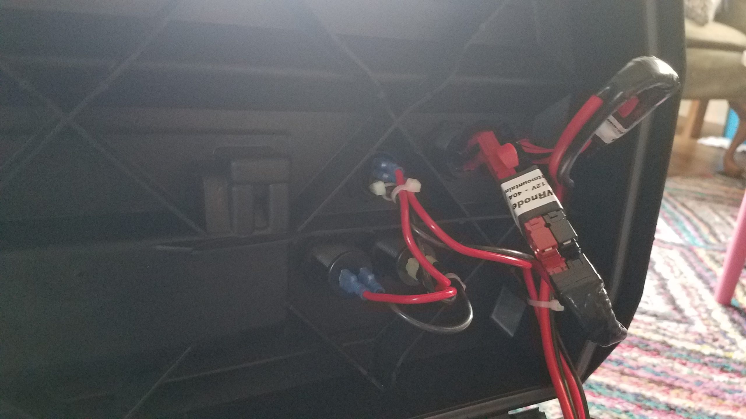
The 100Ah battery was easily charged in about 45 minutes. We’d only drawn about 3.5Ah from the battery running lights, charging a phone, and a portable projector. The panel in use here is a Bioenno 100W folding panel and from the VictronConnect application screenshot it’s charging at about 4.5A. The back view shows how the solar panel is connected to the charging unit and the battery. This is the first time I’ve used the West Mountain Radio Epic PWRGate to charge the 100Ah battery. I’m hoping to use it for charging from a vehicle alternator, an existing DC power supply, or solar panel. I’m also hoping to add a charger like this to the box along with a temperature probe to ensure the battery isn’t charged when it’s too hot or cold. The Relion RB100 has a minimum charging temperature of -4F.
This a detailed view of the West Mountain Radio Epic PWRGate. The green LED indicates it has good solar charging voltage, and the blue LED that was slowly pulsing which indicated that the battery was being bulk charged by the solar panel. The PWRGate is programmed with the specific battery chemistry settings for LiFePO4 batteries and is current limited at 6A for some of the other batteries I charge with this setup.
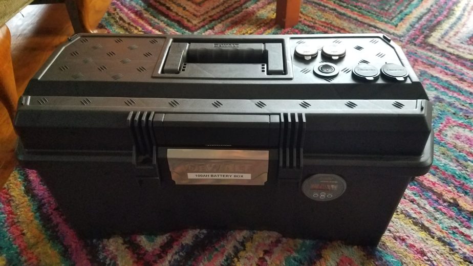
Ok, so this is a big one. I wanted to build a battery box that could keep me going a few days without being able to charge while camping and/or operating. I also wanted accurate power accounting and the ability to understand my power consumption and have alarms when usage exceeds specified thresholds, providing the opportunity to either adjust usage or in an emergency not be surprised when I drop out. I also wanted to design the system for maximum flexibility when it comes to charging and connecting loads. Most commercially-available systems that met capacity and power needs were designed around inverters and larger 30+ volt solar panels that were designed to mount on structures or large vehicles like RVs or vans rather than the smaller and more portable 18v open circuit foldable panels that are used more commonly for my purposes. Having a wider range of panels that I can use is better because it would be good to charge from either so not building in charging was ideal. I also found the options for high-amperage DC connectors lacking in many pre-built options. Some units would have one or two 25A outputs, but those are at the max current range some of my radios will draw at full power. I wanted some breathing room current-wise. In the event I wanted to operate one of my bigger radios at full power I’d rather not risk burning a fuse out or damaging my power source – especially in the field while I’m relying on it. It’s also nice to have many connectors available on the source which eliminates the need for a bunch of splitters. None of the commercially-available options I evaluated provided more than two high amperage connectors. Finally, I wanted a couple USB fast chargers for my and my partner’s devices which many commercial options provided, but they’d typically provide a single fast charging port.
I took some inspiration from a Powerwerx box that a fellow ham and NET team member Laura, KI7ZZQ purchased. That battery box was designed to accommodate a 50-70Ah battery which wouldn’t physically fit any of the 100Ah batteries I had been considering during the design phase, but it provided me a rough template I could build from in terms of layout. As with that box just including power distribution and monitoring in the box was a way I could reuse existing systems I have that perform well without having to buy more of those components. Buying a bunch of new parts is pretty expensive so not including more core devices in the box is definitely a plus.
This was not a cheap project, but I think it’ll be worth it.
Theory and design
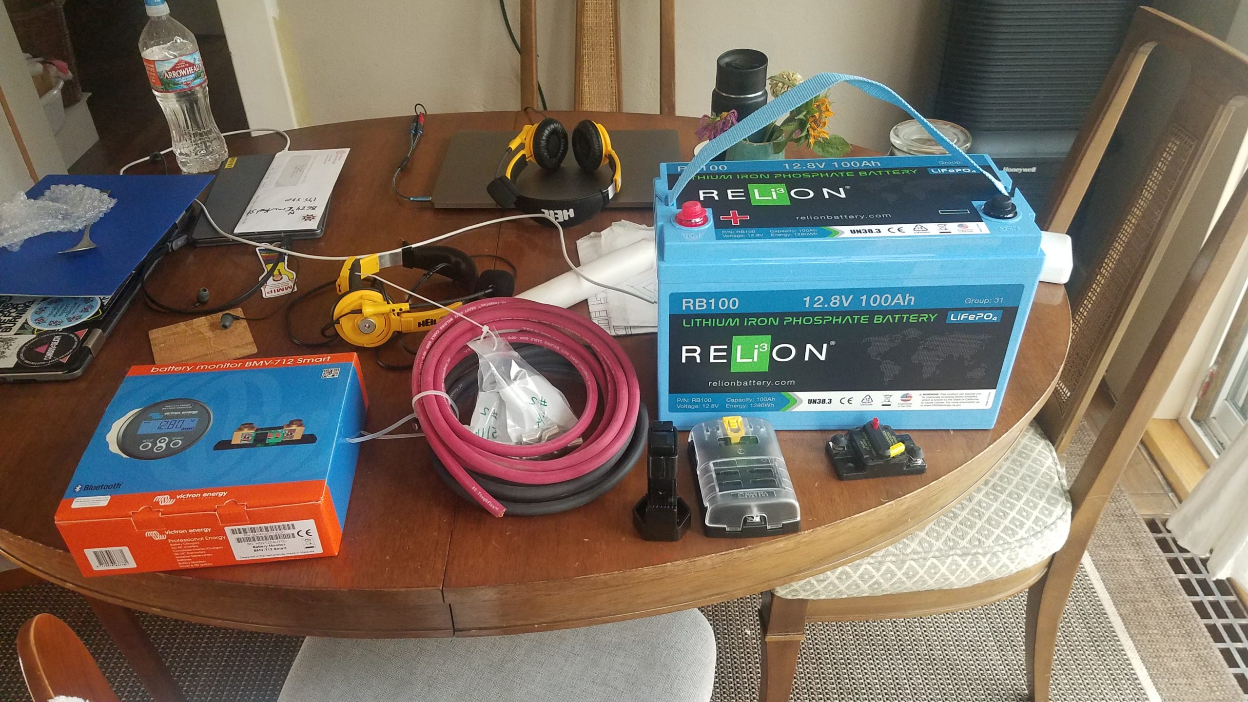
By selecting a 100Ah battery I get 80Ah of usable power from the system without significantly decreasing the battery’s lifecycle. Using LiFePO4 batteries instead of lead-acid means I get an additional 30% depth of discharge without the destructive effects of discharging to 50%… The LiFePO4 battery I selected also weighs 26lbs. A similar capacity lead acid battery would weigh a lot more and probably require a much sturdier and expensive enclosure. Another advantage of LiFePO4 batteries is the lack of battery memory – that is to say the useful lifetime of a battery isn’t diminished by leaving it in a partially-charged state. Some battery technologies suffer from that problem which is a problem if you’re in a situation where you might not be able to completely recharge the battery completely during use. As far as parts go I wanted to attempt to source the parts I didn’t already have from a variety of vendors… I had a preference for smaller and more local vendors, but that didn’t work out 100% of the time. The enclosure (tool box) and a 1 1/8″ hole saw are two examples of where that didn’t work. The bill of materials will list the source of each component.
So let’s start with the system design itself. There are a few core components that I knew I’d probably want from designing a bigger high amperage system when my partner were considering purchasing and building out a van for camping/touring. The core parts that everything else would be designed around are:
100Ah LiFePO4 battery
Reliable battery state and power usage monitoring capability
Battery disconnect for safety and preventing parasitic loads from draining the battery
Circuit breaker for the battery to prevent damage to components or fires
DC subpanel to split out and protect branch circuits
Two switched USB rapid chargers.
Flexible charging – AC-to-DC chargers (wall socket, generator), solar panels of various types, and DC-to-DC (vehicle, independent DC power supply, DC generator outputs)
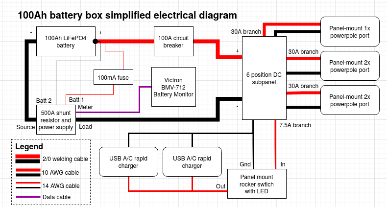
Those components are roughly connected and arranged as follows. Chargers can be connected to any of the powerpole connectors listed below, and so can loads. The only loads that wouldn’t be connected to powerpole connectors are devices directly connected to the built-in USB A/C rapid chargers. You’ll notice there’s a power line running from the battery to the 500A shunt resistor and power supply that feeds the Victron BMV-712 through a 100mA fuse, bypassing the circuit breaker which also doubles as a battery disconnect. That’s intentional as the BMV-712 requires constant power to track battery state and if powered off it will lose its zero-point configuration. This is the only parasitic load that isn’t switched in this system apart from the BMS built into the battery, but it’s required to get accurate battery status so I compromised.
Used to drill holes in plastic fins in toolbox for zip ties
N
Electric drill
1
?
?
?
Used w/hole saws and drill bits
Y
2″ hole saw
1
?
?
?
Used to drill a hole for the Victron BMV-712 panel
Y
Phillips screw driver
1
?
?
?
Y
Metal shears
1
?
?
?
Used to cut #2/0 welding cable
Y
Diagonal cutters
1
?
?
?
Y
Socket wrench
1
?
?
?
Y
?mm socket
1
?
?
?
Used for shunt bolts
Y
?mm socket
1
?
?
?
Used for battery terminal bolts
Y
?mm socket
1
?
?
?
Used for #10 nuts
Y
?mm socket
1
?
?
?
Used for DC subpanel 100A contacts
Needle nose pliers
1
?
?
?
Used to help pull wires, tighten panel mount nuts
Y
Claw hammer
1
?
?
?
Used w/ the TE hammer-type crimping tool
Y
Pocket knife ******
1
?
?
?
Y
Legend ? Can’t remember/unknown — Same as above * Includes spare(s) or extra(s) ** This is small-cell plastic foam used as packing to keep the battery from moving around a lot *** Used mostly to bind wires and as extra insulation on the #2/0 ring terminals. Also used to physically shore connections up due to gaps in wire jacketing or potential stress points from bends. **** Used as insurance to hold the toolbox closed in case the latch is opened unintentionally ***** Doubles as a battery disconnect switch ****** Used to clean plastic burrs left from the hole saws and to cut the jacketing on the #2/0 cable in preparation for crimping
Assembly
This was done in a a couple phases – in part because I was waiting for things to come in the mail, and in part because I sort of “winged it” building this out in terms of mounting components to the enclosure. The first thing I did was pick locations for each of the high amperage components: the battery, BMV-712’s 500A shunt, 100A circuit breaker, and the DC subpanel. I made sure to allow for enough space to run cables to and from each component before drilling holes for them. The battery was pushed to the left side of the tool box. This makes it a bit awkward to carry but creates enough space in the right side to mount everything.
Once I found a good placement for the components that required mounting I just drilled holes in the enclosure using the components as a template. For each component I drilled an initial hole and inserted one of the #10-24 cap screws in the hole to hold it. I then drilled out a second mount and placed another bolt in it. After I’d placed all the components and got the holes drilled for them I added the #10 bonded washers with the neoprene side on the outside of the enclosure. To minimize jagged edges from threads on the outside of the enclosure I put the phillips end of the cap screws on the outside as well. The nuts and lock washers were placed on the inside.
The next step was to route, measure, and cut the high amperage #2/0 welding cable between each component. I did a dry run of the cable from component to component and cut each piece to length. I ran a piece of from the negative battery post bolt to the BMV-712 shunt battery terminal, cut it, ran another piece from the shunt to the negative terminal of the DC subpanel to the BMV-712 shunt load terminal, and cut it. I then took the red #2/0 welding cable and ran it from the positive terminal on the DC subpanel to the 100A circuit breaker, cut it, and then ran another piece from the circuit breaker to the positive battery terminal, and then cut it.
For each piece of #2/0 welding cable I cut I stripped enough jacketing off of the end to fix the appropriate #2/0 lug ring terminal to the wire. Make sure the hole on each lug ring terminal matches the post you’re planning to connect it to. It’s worth double-checking before you crimp since each section of wire is cut to length. After verifying that I was using the right ring terminal for each connection I crimped them to the #2/0 welding cable. I then wrapped the bare metal parts of the lugs that might be prone to shorting with electrical tape since I didn’t have any heat shrink tubing. I also used the tape to shore the joint between the jacketing of the welding cable and crimp-on connector.
The next step is to hook the high amperage wire up to each component. This will help us figure out where to run the legs from the DC subpanel and to help us properly place the panel mount components without interfering with the high amperage wire runs and components mounted inside the enclosure. Before making the connections between components verify the polarity of the connections and break the circuit by pressing the reset button on the circuit breaker. The connections should be made according the the simplified wiring diagram above.
Completed mounting of all components in the lower portion of the enclosureCompleted mounting of all components in the lower portion of the enclosure
The next step is to place and mark each panel mount component. I chose to mount the BMV-712’s meter on the front of the tool box to the right of the latch since I mounted the DC subpanel on the flat part of right end of the toolbox. I mounted the 1x powerpole panel mount component on one of the angled surfaces on the right end of the enclosure so I could connect a charger easily when it’s stored on a shelf. I picked spots for the panel mount components on the lid because I think that’s going to be the easiest spot to make connections in the field. All the panel mount components were placed in such a way that the panel mount nuts cleared the plastic “fins” on the inside of the enclosure. Special care should be taken when placing components in the lid. There are a lot of plastic fins on the inside of the lid. Use the 2″ hole saw to cut the hole for the Victron BMV-712’s meter, and for all the other Powerwerx panel mount components use the 1 1/8″ hole saw. You might need to shave the decorative raised lines on the lid down with a pocket knife to ensure that the panel mount components mate to the outside of the lid properly.
Photo showing placement of all panel mount components
At this point it’s time to start making the connections from the subpanel to the panel mount powerpole connectors. Since I used 10GA wire capable of handling 30A it’s hard to daisy chain between ports so I opted to use some PWRNode splitters to make the connections to the 2x panel mount powerpole sockets. I made some shorter 2″ stubs of 10GA wire and crimped 45A powerpole conductors on both ends of each stub. Connecting all 4 ports requires 8 2″ stubs. Once I crimped the 45A conductors on I added the powerpole housings to one side of each stub. The other side of the stub was inserted into the panel mount connector. Each panel mount socket is connected to a single run of cable from the DC subpanel with powerpole connectors on the end of it. The idea is that each socket can support up to 30A of total current draw. Once that was complete the side with the housings were connected to the PWRNodes and powerpole retention clips were installed to keep all the powerpole connectors in place. The 1x powerpole connector was run directly to the DC subpanel. Each leg was then fused in the DC subpanel with a 30A fuse. I used some electrical tape to support the “joints” between the powerpole connectors that lead to the DC subpanel and the powerpole connectors themselves.
The next step in wiring the system is to connect the panel mount chargers in parallel and switch them with the rocker switch using the 14GA wire. This is accomplished using the connections as detailed in the simplified electrical diagram. The brass connector on the switch connects to the ground, the middle connector connects to the DC subpanel, and the silver connection on the end connects to the USB chargers wired in parallel. The photo below details how the connections to the panel mounted devices and sockets. I drilled a hole in one of the fins on the lid of the toolbox and wire tied the wires coming from the DC subpanel to the lid to keep the wires from migrating a lot during transport. I also used wire ties to hold some of the wires together coming out of the individual parts.
Now that all those connections are complete we can re-connect the battery, and while we’re at that we’ll hook the BMV-712 up. The BMV-712’s box has a handy connection diagram. In this step we’ll connect the battery and the BMV-712. First connect the BMV-712’s red (positive) wire connected to the temperature sensor lug to the battery using the ring terminal along with the terminal on the #2/0 welding cable. Both should connect directly to the positive battery terminal. Take care not to short the pin end of the BMV-712’s red power cable while connecting it. Once that’s connected to the positive battery terminal connect it to the B1 pin on the BMV-712’s shunt, and connect the black temperature monitor cable to B2 on the BMV-712’s shunt. The BMV-712’s manual will detail how that connection should be made. Now connect the gray 6-pin modular data cable from the shunt to the BMV-712’s panel mount meter. Once that’s been hooked up you can connect the negative battery terminal to the black wire leading to the battery side of the BMV-712 shunt. When properly connected the panel should light up blue and the display should become active. [Note: this was updated to include directions to connect a BMV-712 temperature sensor.]
Once all these connections are made and the battery is re-installed make sure you install a 7.5A fuse in the subpanel on the leg that connects to the USB chargers. If the 7.5A fuse blows during testing one or both of the USB chargers are wired backward. Use the + and – on the bottom to properly wire the positive and negative sides of the charger. Install 30A fuses on each leg that leads to powerpole panel mount sockets.
Now we’ll pull the yellow reset bar on the breaker back in to energize the DC subpanel. Once the subpanel is energized we can test the USB charger leg of the circuit by activating the toggle switch. The red LED should activate on the toggle switch, and both USB chargers should show their voltage with blue numerical LED displays. If all three of those work that’s wired correctly.
As a bonus I added some scraps of plastic closed cell packing “foam” around the battery to dampen vibration and shock to help hold the battery in place.
The installation is complete we can move onto programming the Victron BMV-712.
Configuring the Victron BMV-712
At this point we should set up the battery monitor. Some of the instructions in this section come in part from instructions provided to me by LightHarvest Solar. I modified some of the values in the configuration to better fit my use-case. The instructions in this section assume you’ve charged the battery completely using an appropriate LiFePO4 battery charger. I used the Bioenno charger listed in the bill of materials to fully charge the battery before configuring the BMV-712. To begin you’ll want to install the VictronConnect app on a device that it supports which also has Bluetooth. There are versions for IOS and Android.
After opening the app you’ll want to select your BMV-712 and pair with it. I also recommend changing the BMV-712’s pin to make sure someone doesn’t pair with it and modify its settings, especially if you’re around RVs or others with a Victron battery monitor. You can then modify the settings on the device. The major configuration tasks to do are configuring the parameters for your battery and doing a zero-point reset once your battery has been fully charged. To begin with we’ll configure the battery monitor with the properties of the Relion RB100. You can leave all the settings as defaults unless they’re specified below. I got the initial values and instructions to configure the battery monitor from LightHarvest Solar. It was provided with the purchase of the BMV-712. After opening settings and choosing “Battery” set the following:
Battery capacity: 100Ah (this is a 100Ah battery)
Charged voltage: 13.9V
Discharge floor: 20% (This is the lowest capacity you want the battery at)
Peukert exponent: 1.00
Charge efficiency factor: 99%
Current threshold: 0.10A
Time-to-go averaging period
Optionally, you can configure alarms for the system. I turned on the alarm buzzer and set the “Low SOC alarm” to go off at 40% and clear at 45%. Since you don’t want to draw the battery down lower than 20% I picked 40% to give me a warning well before I draw it down. If you draw the battery down below the discharge floor it can be damaged. You can also optionally configure a temperature alarm if you have the BMV-712 battery temperature sensor. See the “updates” section at the bottom of this post for details.
Once the battery has been configured and ALL loads and chargers except the BMV-712 have been disconnected you can then click the “synchronize” button, and then click “calibration”. Synchronize sets the battery state-of-charge to 100%. Calibration zeroes out the current measurement on the shunt resistor. If you disconnect the battery monitor you’ll need to redo this part of the process starting with a full charge.
Using the BMV-712
While this post is mostly focused on the app the display panel on the BMV-712 can display the status information using the arrow keys on the front panel. Navigating that is pretty easy, but I’d also recommend reading the manual as there’s more to the panel than just displaying data. The most common screens I use in the app are the device list which is used to manage Victron devices. They have an entire ecosystem of devices that can be managed and monitored from this app. I go through this to connect to my battery box. The battery box has been renamed in the settings (gear icon seen in the other screens). The status page shows you all the current stats for your battery – state of charge, voltage levels, current, and power. There’s one thing that’s cut off at the bottom which is the status of the control panel’s relays. For my configuration the relay is open since it’s not really doing anything. The history tab shows you stats for your battery over time. This data can be cleared, but it’s nice to understand what you’ve done with your battery over time so I probably won’t be clearing that until I replace the battery in the system. The trends tab is really nice to use when you’re watching your battery in real time from within the app. You don’t get data points when your app isn’t connected unless you get a Victron Cerbro GX or similar device but that’s overkill for my use-case.
Device selection screen
Battery status
Battery history
Battery trends
Problems left to solve
There are still some problems to solve. I need to install some sort of barrier that prevents the battery from moving to the right inside the enclosure. I’m thinking about bolting a barrier into the enclosure to prevent too much movement. The toggle switch on the top isn’t weather resistant either. The toggle switch comes with a plastic cover but it’s impossible to install without the rocker switch popping out of the panel mount.
Updates
I decided to add a temperature sensor to the BMV-712 in order to make sure I’d get an alarm if the battery was out of the appropriate range to charge which is a more narrow range than the discharging temperature. The changes I made to connect the battery temperature sensor was to purchase a temperature sensor for $25. I disconnected the old wire running from the positive battery terminal to the current shunt, connected the new one, and connected the new larger lug to the battery terminal. I then connected the black wire for the temperature sensor to the open input on the shunt. After that I configured the BMV-712 to use the second input as a temperature sensor using the web application. Then I configured my high temperature trip temp to 55C and the high temperature clear to 53C. The alarm will go off 5C before the battery’s charge limit of 60C. The low temperature alarm was set to -15C and the low temperature clear was set to -13C. -15C is 5C above the battery’s minimum charging temperature limit of -20C. The connection diagram has been updated to reflect the new temperature sensor connection. This post talks about recently implemented changes to the battery box.
Hello all, it’s about time I wrote a post about my camping trip my partner and I took a couple weeks ago. I took my trusty Lab599 TX-500 kit, a couple 20W GoalZero Nomad solar panels, headset, and table/chair combo up camping with our “new” 4×4. I wanted to do some HF QRP and some handheld UHF/VHF operation while I was out. I brought some of the same portable furniture that I used at the beach last post since it worked out so well.
The view was pretty sweet for this one. The smoke from the wildfires made everything a bit more hazy but pretty great none-the-less.
View while operating
While operating HF I made a number of contacts, and the solar panels kept the 4.5Ah Bioenno LiFePO4 battery built into the HF QRP radio kit charged the whole day. The first HF contact I made was with Stefan, AF6SA who was working POTA in Eldorado Natoinal Forest (K-4455). His signal was 5/6 on at about 450 miles away on 20m. I also made a contact with VA3AAA, Stanley in Ontario, Canada. I was pretty excited to reach Ontario with a low power radio. That contact was also logged on 20m. I also made a contact with the K0GQ radio club in MO on 20m. All of these contacts were made between 5 and 10w using the Trail-friendly EndFedz EFT-10/20/40 antenna strung between a couple trees about 50′ apart and about 25′ above the ground.
I switched radios and bands to see if I could get into some of the repeaters in the Portland area (I could) with my Yaesu FT3DR and a Signal Stick antenna. I ended up on 2m and caught two hams on 146.520Mhz doing a SOTA activation: K7AHR and K7IW. I think they were on Lookout Mountain, but I can’t remember and didn’t properly log it. I was running 5W for those contacts.
Howdy and welcome back! I spent the day at Rooster Rock, a clothing-optional beach on the banks of the Sandy River in Oregon. Since I burn easily I got a cheap tent from Target to get very sandy and to keep me and my gear safe from the sun! As a bonus this specific tent actually has a pass through for cables in the front corner to the left of the door which is pretty great for running solar panel connectors and feed line. I didn’t have any successful contacts, but that’s not surprising given the difficulties I had tuning the Superantenna. I couldn’t manage to get a decent SWR on the QRP radio. The real point of the post is about portable shelter options that can keep you out an entire day even when you’re literally naked. This was able to keep me and the gear cool enough to keep going. Folding a corner of the tent up allowed the interior mesh to breathe away from the sun. In the picture below you can see through the door that the rain fly has been lifted.
We weren’t able to get the best spot but at least we got something out of the way on a path and had enough space to set the tent up. I had enough clear space to keep the solar panels going all day as well. They kept the battery kept everything charged and running. I tried to see if I could make any UHF/VHF contacts but I was in a gorge so I had very limited luck. I’m sure you’re just as shocked as I am. I then tuned the Superantenna as best I could for 20m and tried to make some contacts but I wasn’t getting out. I heard a bunch of stations on the east coast and in the midwest including participating in a New England radio event or QSO party for the 4th of July weekend. I wasn’t able to get out to anyone though. In addition to those stations I could also hear but not reach Paolo IK5SRF in Tuscany, Italy. Paolo had quite the pileup going.
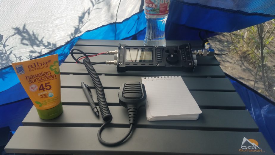
A view of the radio setup, the table, and chair. This three-legged chair is actually pretty comfortable.
My conspicuously-empty log book with only notes and the radio.
At the end of the day breaking the tent down was pretty easy. We were able to tear down the entire site and radio station in about an hour, have it loaded into the beach wagon and off we were. Much of that time was as usual rolling feed line so it’s not a pain to unroll later.
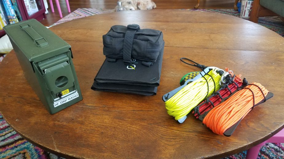
HF QRP radio kit, solar charging kit, antenna hanging kit
Howdy all! This is a new post about my portable QRP radio kit and it supporting kits based around my Lab599 TX-500. Its a fairly self-contained kit but doesn’t have a couple key elements included in the actual box. It doesn’t have any equipment to hang the included trail friendly end-fed half wave dipole or battery charging equipment. I’ll include those elements in this post as well, but they don’t live in the HF radio kit itself. This will be a long post so strap in!
The QRP radio kit
Let’s start with how the HF radio kit is built out. It’s based around a small ammo can I got at a discount store. I wanted to have a fairly self-contained kit that was water resistant and durable and I also wanted the ability to charge and use the battery with the ammo can lid closed to protect against water and dust and ingress. This is by no means waterproof but I wanted to make sure it was at least splash and rain resistant since I do a lot of operating in the Pacific Northwest region of the US which is notorious for its rainy weather.
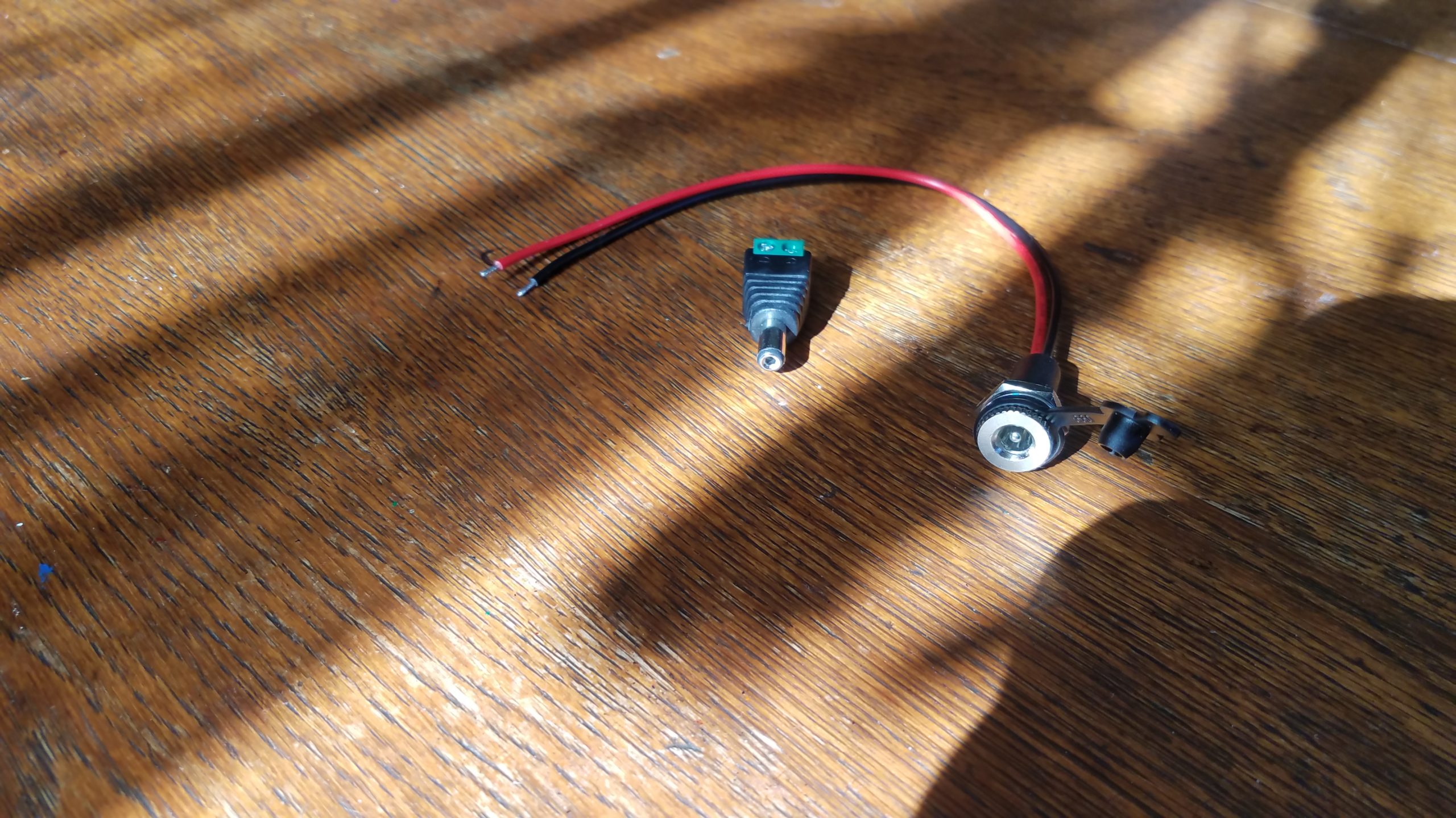
DC barrel connectorsTesting charger and connector fit
The kit’s battery is a 4.5Ah Bioenno LiFePO4 pack. In order to make sure I can leave that battery in the kit I had to devise a way to connect it to an external charger through the can. After calling the folks at Bioenno I was able to determine the barrel connectors included on their batteries are 5.2 x 2.1mm connectors. The panel mount water resistant connectors I used have 18 gauge wire that supports a max of 10A at 12V DC. I was also able to track down a pack of screw-on terminal barrel connectors as well to connect the battery inside the ammo can. This setup also allows the battery can stay inside the case while the radio is being operated which is good for water and dust resistance. I recommend testing your connections before you drill for both polarity and appropriate voltage levels. In my case they worked fine so I proceeded…
DC panel mount connector installed in case and insulated screw terminal connector installed
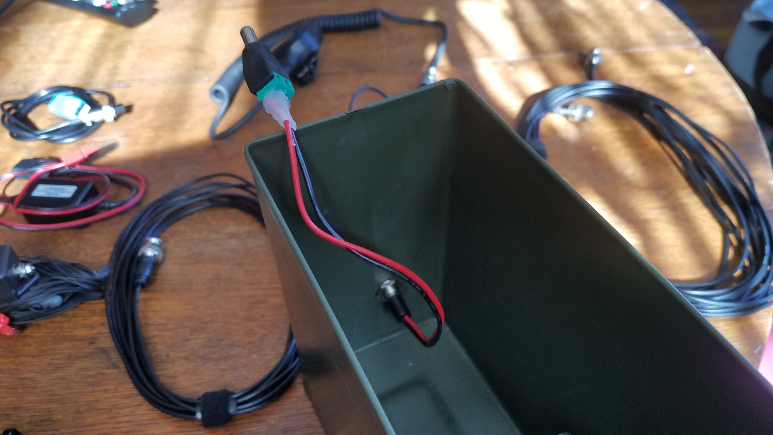
The first consideration in installing the connector is making sure the connector doesn’t interfere with the mechanism on the case that opens/closes it. After that you have to worry about the connector and wire on the inside of the case interfering with items in the case when it’s packed. I decided to place the connector in such a way that the radio laying on its side against the wall of the case would rest against the installed connector. Using a simple metal drill bit I was able to make a hole big enough for the panel mount connector just below the latch mechanism. I then removed any metal burs from the drilled hole and any turnings from the inside of the can to prevent rust, scratching, and short circuits. After installing the panel mount jack and the rubber water/dust cap I just screwed the positive and negative wires into the barrel connector that will hook up to the battery. To ensure no small metal parts caused a short I used hot glue to insulate and strengthen the connection points on the screw terminal barrel connector.
4.5Ah battery installed in the corner of the ammo canBattery connected to external DC barrel connector
The next step is adding the battery to the ammo can. I wanted the battery to be semi-permanently mounted in the box so I opted to use 2 x 4″ Velcro strips to secure the battery to two surfaces in the box. the link for those strips is to Amazon but similar strips are available at many stores and websites. The optimum position for the battery seemed to be in a corner where I could install Velcro strips on two of the faces of the corner making it removable without drilling more hols in the can or dealing with metal and glue. Fit testing your equipment is also important when deciding where the battery will be installed. I did that by attaching the loop side of the 2 x 4″ Velcro strips I cut to size to the battery but not removing the plastic that would go on the hook side of the Velcro intended for the inside of the can. Once I was satisfied with the location of the battery and my ability to pack the kit I removed the plastic backing from the hook side of the Velcro and stuck the battery in against the back and corner of the can. I was then able to connect the pass through electrical connection and make sure everything worked properly including polarization of the battery connection. Failing to test the polarity could result in damage to equipment or even potential issues that would compromise the battery. It should also be noted that the radio’s rubber feet make the fit against the battery very tight.
Kit contents + Bioenno 2A AC-DC charger
Here’s the contents of the kit. Left to right, top to bottom.
Ammo can body with battery and pass through DC cable installed.
Plastic bag to hold small adapters and connectors.
Ammo can lid
Bioenno 2A AC to DC charger for LiFePO4 batteries
Lab599 TX-500 speaker mic and Raspberry Pi 4 dedicated to the kit
2x 25′ RG-174U cables w/BNC ends (multiple segments of shorter cable allow me to make the shortest connection possible for a given deployment)
15′ RG-174U cable w/BNC ends
DIY REM/DATA GX12-7 connector for the TX-500 with a 1/8″ TRRS end connected to a Millso TRRS USB sound card
TX-500 USB CAT cable (stock cable that comes w/radio)
Par EndFedz trail-friendly EFT-10/20/40m antenna on winder w/BNC connector. This has some red paracord loops attached at each end of the antenna for easier connection to support lines and for visibility.
Powerwerx USBbuddy w/spliced-on USB-C connector for the dedicated Raspberry Pi 4. The splice minimizes cable length for less voltage drop and excess cable.
TX-500 radio w/3D printed GX-12 series connector dust caps caps installed
2x DIY 5.2 x 2.1mm barrel connector to Anderson Powerpole adapter cables
2x 6″ USB A to MicroUSB cables to connect devices for charging
2x 6″ USB A to USB C cables to connect devices for charging
W2ENY headset adapter wired for a dynamic mic. (The included adapter with the TX-500 was defective from the start in such a way that I’d have to significantly shorten the cable, and I also wanted to use a different PTT button and my existing Heil headset with a dynamic mic element)
2x BNC barrel connectors to connect feed line segments together
1/4″ to 1/8″ TS adapter for PTT switches
1/8″ to 1/8″ TRS to TS adapter for ear buds connected to the speaker mic
90 degree male to female PL-239/SO-239 connector (convenience)
BNC to PL-230/SO-239 male adapter (for connecting to most of my other antennas)
DIY 1/8″ TS PTT button made from spare parts I had lying around
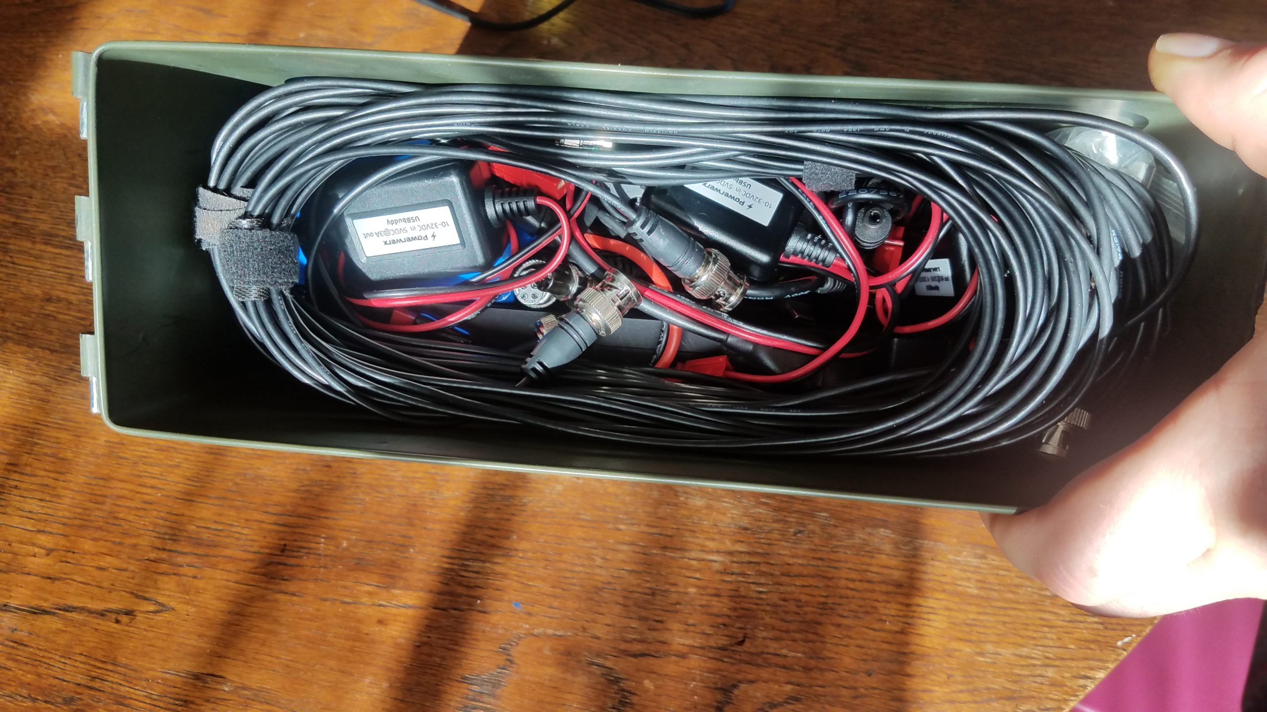
Putting the kit together layer-by-layer is pretty easy. The below photos illustrate how the kit is packed in 3 layers – bottom to top.
The first layer at the bottom of the kit – battery, radio, Raspberry Pi, RPi USB C power converter, adpater/connector bag, radio power cable, Powerpole to barrel connector adapters, TX-500 data and CAT cable. The middle layer of the packed kit – 2x USB buddies, all coiled feed lineThe top layer of the packed kit – Speaker mic and its cable coiled around the trail-friendly antenna
Solar power kit
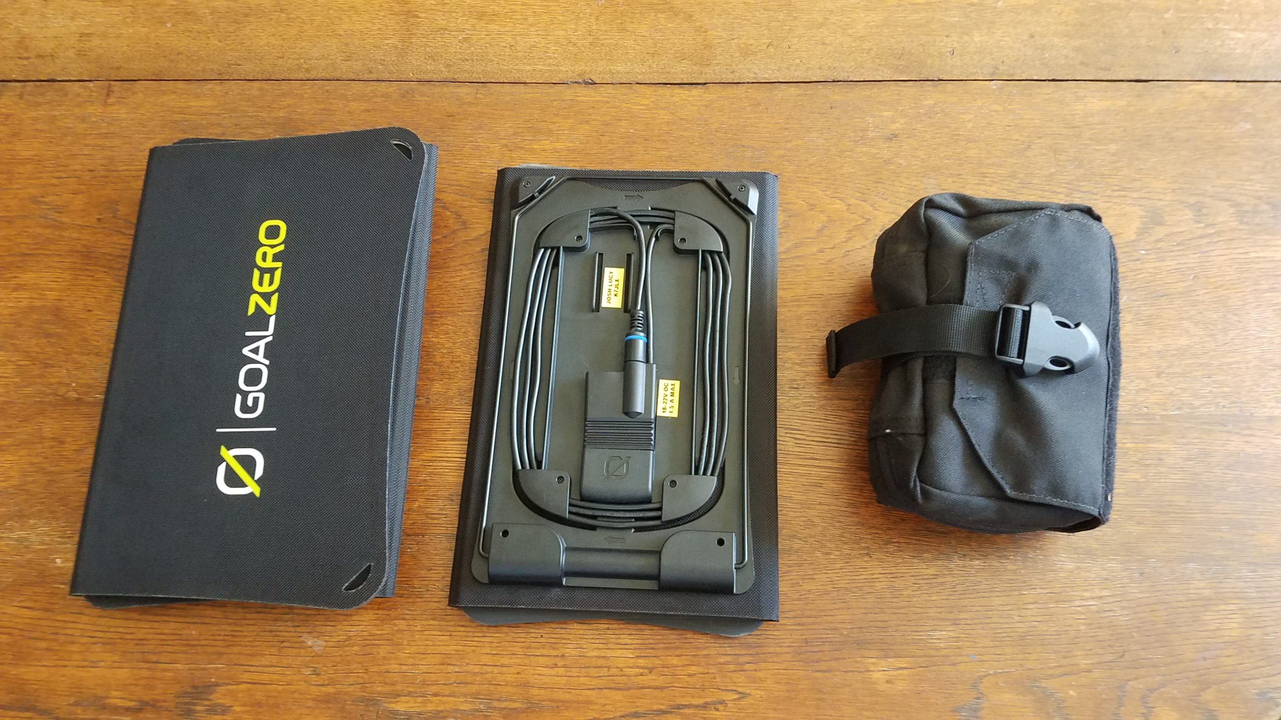
Now that we’ve covered the kit contents let’s talk field charging with solar power! The solar charging system I typically bring with this radio uses one or two 20W Goal Zero Nomad 20 folding solar panels. Those attach to a Buddipole PowerMini charge controller and power meter. Much of this solar charging kit is composed of cables, but it’s designed to be used with a number of my radios, batteries, portable lights, and USB device chargers.
Two solar panels and the charger kit
Depending on the deployment I may bring one or both solar panels with the charger kit, or sometimes I’ll just bring the charger kit for power metering to understand how much I’ve drawn my batteries down and at what rate I’m using power. You can check the Buddipole PowerMini’s product page to learn more about it and ways it can be used. In some cases with good sunlight a single 20W panel can provide around 1A (typical max power I’ve gotten from the panels), but in overcast conditions I might use both panels to get 1A peak power. It also might be a good idea to bring both panels to charge at about 2A. It’s especially nice if I expect to charge a phone/tablet and run a radio with a Raspberry Pi if I’m using data modes.
In the above photo you can see the two Goal Zero Nomand 20 solar panels. One of them is staged to show the top view of the panel and the other the bottom view. Each panel has a kick stand to hold itself up at various angles on the ground, cable with an 8mm plug, a USB charging port, and holes in the corners of the panel to suspend them. The Nomad 20s fold open to reveal three solar cells.
Charger kit openedDisassembled charger kit
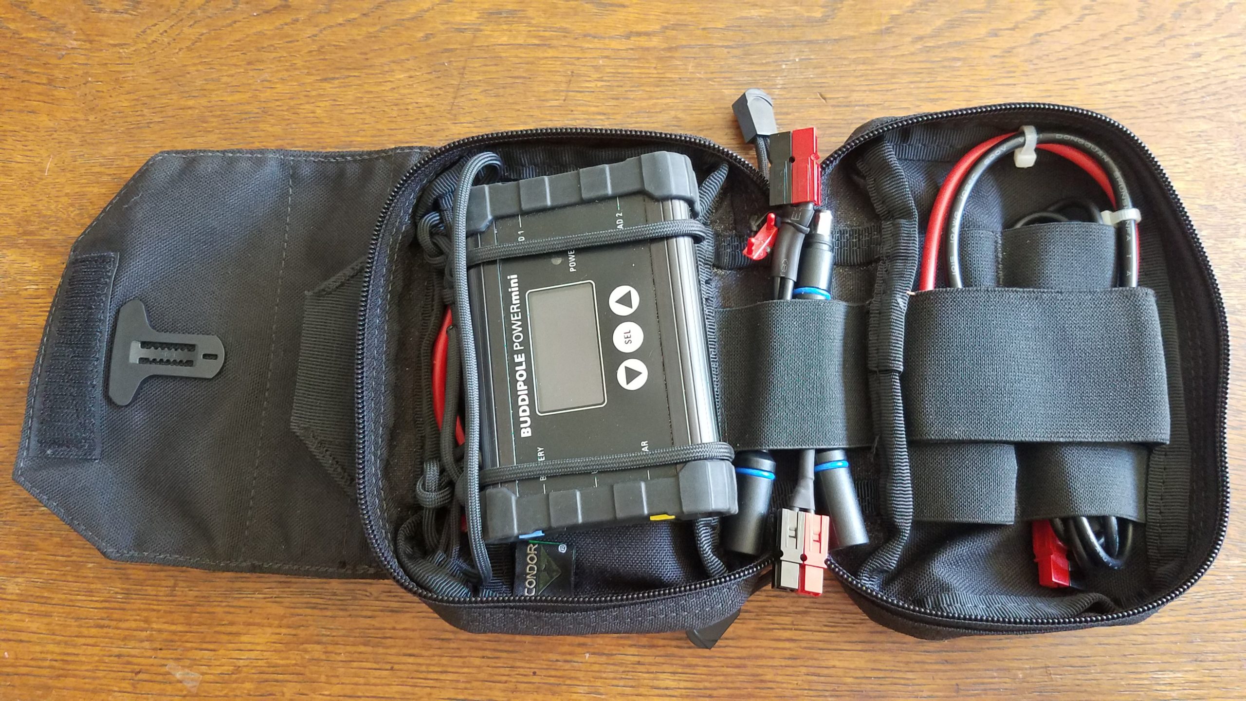
The solar charger kit consists of a Condor MOLLE compatible pouch that has a detachable main pocket which allows you to install and remove the pocket without disconnecting the MOLLE part from the webbing, and also has a loop for easily suspending hanging the kit from something. The kit contains the following items:
Condor MOLLE compatible pouch w/ paracord loops to hold and suspend the Buddipole PowerMini
Condor MOLLE compatible pouch attachment platform. This comes as a single unit with the pouch listed above.
West Mountain Radio PWRNode (4-way Anderson Powerpole connector)
DIY MC-4 to Anderson Powerpole connector (for a 100W solar panel not pictured here)
BuddiPole PowerMini
DIY 2.5″ Anderson Powerpole jumper cable w/10 GA wire (rated for 30A @ 12V DC)
DIY 6″ Anderson Powerpole jumper cable w/10 GA wire (rated for 30A @ 12V DC)
DIY 4″ Anderson Powerpole to Goal Zero male 8mm connector pigtail.
DIY 4″ dual Goal Zero female 8mm plug to Anderson Powerpole pigtail. This allows the two Goal Zero solar panels to be used simultaneously.
DIY 3′ Female Goal Zero 8mm to Anderson Powerpole cable.
You’ll probably notice there are a lot of seemingly redundant connectors and pigtails in this kit. There’s a reason I carry so many adapters around, and that is to make sure I can run as little cable as possible to achieve connections between system components. Being able to use shorter cables help limit voltage drop, but having the option to use a longer cable to connect the solar panels might mean I can stay in the shade and keep my solar panels in the sun. The short Anderson Powerpole jumpers included in the kit can help me connect to the battery or connect a PWRNode to the PowerMini. The Anderson Powerpole connectors on the side of the PowerMini don’t allow you to connect the PWRNode directly to it, and even if they did you’d lose two of the four connections on the PowerMini side of the PWRNode. In most cases this kit powers the entire radio doing phone and data, a phone and tablet, etc. Most of the time the equipment barely uses the battery while operating during the day and I have a full battery to use at night for the radio and lights.
Antenna hanging kit
Antenna hanging kit
Last but not least we have the antenna hanging kit. It’s great to have a radio and a way to power it, but if you can’t get your antenna where it needs to be it’s all for nothing. This part of the kit rounds off the portable radio station. It’s designed to work with a number of wire antennas I have – a Par EndFedz 6m antenna, the Chameleon EMCOMM III Portable, and the Par EndFedz EFT-10/20/40 trail friendly antenna that lives in the HF radio kit. In the case of the trail friendly antenna we require two points of suspension for horizontal dipole operation – the end of the wire antenna and the transformer component. Being in Oregon and setting up my radio station in the region quite a bit I frequently rely on trees as antenna supports, and thus also pack an arborist’s weight as part of my equipment to assist in hanging the line. It adds a lot of weight but is definitely worth it. Using rocks and other tree branches works but definitely comes with snagging risks and the possibility your line will come off of the wight you’re using to get the line up… especially when it comes to rocks. I carry 4 aluminum tent stakes with paracord loops and quick links for attaching line. Those are bound during transport by a piece of paracord I tied together to make the clanking of the tent stakes go away and to keep them from flopping everywhere. There are four aluminum tent stakes in the kit because I might want to anchor my Chameleon EMCOMM III in 3 or 4 spots depending on antenna configuration. I have two 75′ high visibility paracord hanks wound around Chameleon wire winders that can support two ends of antennas that are in a horizontal dipole configuration. Each hank of paracord has a quick link attached for connecting to the ends of an antenna or suspension point, and the arborist’s weight for deployment. I can leave one of the paracord hanks behind if I want to set an antenna up in a configuration that only requires one suspension point like an inverted V. I added a small loop of paracord to the Chameleon wire winders in one of the corner holes to take the weight of the assembly off of the elastic band that wraps the paracord when the hank is being stored or transported. The locking carabiner is used to hold everything together, clip the kit onto something like a backpack, or hang it from a pocket during setup. The specific carabiner I’m using is probably overkill but I had it laying around so I used it. There’s also another loop of paracord attached to the carabiner which acts as a more comfortable carrying handle and for storage by hanging from a door knob.
The antenna hanger kit broken down to (most) of its individual components
Black paracord cut small into smaller pieces for use as a handle, 2x wire winder strain relief loops, and a keeper for the tent stakes (don’t ask me how I figured out how to tie that. I can’t really tell you how I did it except that I did a lot of experimentation.
2x Chameleon wire winders
6x threaded quick links (4 on stakes, 2 on the 75′ paracord)
2x high visibility 75 ft paracord hanks w/ 3M high visibility strip included for working on the antenna suspension at night
Tent stake holder assembled
Note the paracord attachment point run through the quick links that make sure they don’t come out of the holder or make a bunch of noise. Both loops of black paracord go through the carabiner, but if you remove the attachment point with the quick links from the carabiner it’s easy to just pull the quick links off.
75′ high vis paracord wrapped around Chameleon wire winder and set up for transport
This is a more detailed view of one of the two paracord hanks. Both are set up the same way. The paracord is wrapped around the Chameleon wire winder and is held on the winder using the built-in elastic band which is wrapped around the paracord and secured with the pictured notches. The quick link is attached to the throw/attachment end of the paracord, and the quick link is also attached to the small black loop of paracord to take strain off of the elastic band during transport. This design uses the quick link, black paracord loop, and plastic wire winder plate to take the weight of the assembly when attached to the carabiner.
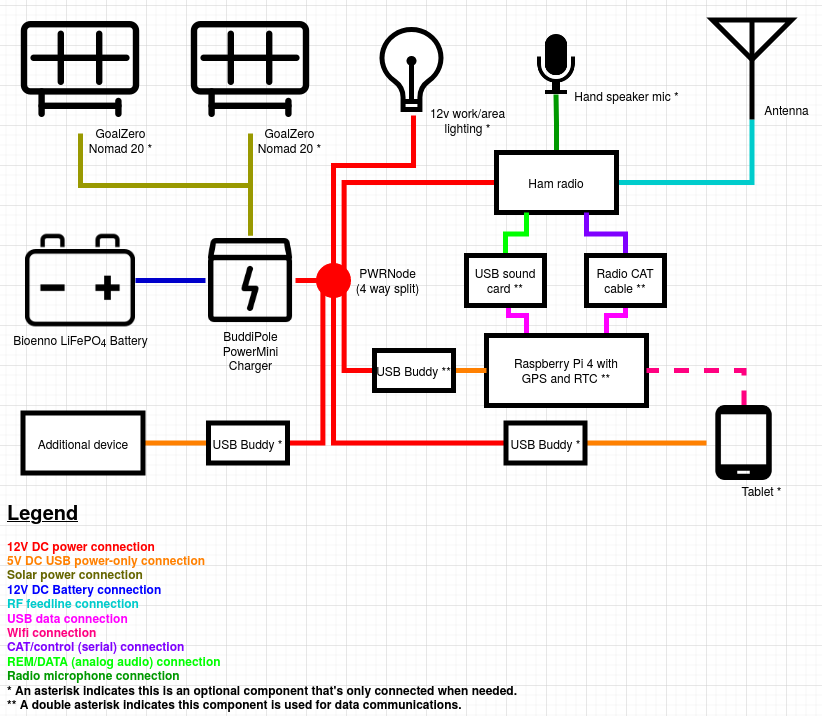
Connecting it all
While this isn’t necessarily directly related to the composition of the kits I described above I decided to diagram out how the station is wired up for my typical use and add this section after I wrote the original post. You’ll note that some components are only used in data operations, and some are only hooked up when needed. For example, I won’t need the light unless it’s dark, I won’t want to use the Raspberry Pi unless I’m doing data comms or using the documentation server. In addition I won’t have any of the USB buddies that I don’t need hooked up at any time because they draw power, and unless I want that power to go to something I just won’t use it. If I’m deploying at night and don’t expect to stick around until morning I won’t deploy the solar panels and add the hassle of managing those additional cables and connections. In any case, this is basically how it’s all wired up for my typical deployments. Sometimes I’ll use different components such as a 100W solar panel instead of the 20s, or add a travel router and a USB buddy to the data deployment depending on my situation and available power/battery.
Wrapping it up
So, this is the kits! I don’t always use the trail-friendly antenna with this radio, but it’s what I include in the kit by default. I also use a Samsung Galaxy tablet and sometimes a customized travel wireless router in conjunction with this kit when I do data mode work to interact with the Raspberry Pi 4 in this kit and / or one of the other ones I have set up, but that’s a whole other post.
Alright, so, all this actually happened on May 29th. I just haven’t been able to sit down a put a post together so here we go! My partner and I decided to take a trip out to Oakridge, OR to avoid the setup for camping but to at least see some sweet nature (nature is neat). Read this before following that link. Naturally I decided to take the opportunity to do some transmitting, and the setup at Salt Creek Falls was the only setup I documented so here it is. We started by following the trail down to the lower observation area at the falls which is pretty great. It was a hot day and the mist coming from the bottom of the falls was pretty refreshing. I climbed back up to the top of the path to make a sked, or, prearranged SSB contact with Kevin, K7AJK in Portland, OR. I also grabbed some water from a stream on the way up for my Sawyer straw.
Salt Creek FallsBag full loaded with a radio station, food, water, etc.
It only took about 35 minutes to set the station up. Most of that was me failing like a complete amateur to get the paracord where I wanted it in two trees that were spaced about 80 feet apart using an arborist’s throw weight. For this contact we were going to attempt to do 80m NVIS so I strung my Chameleon EMCOMM III portable in a horizontal configuration, which is the configuration recommended by Chameleon for NVIS work. I have some bad pictures of both paracord runs attached to the antenna below, but because they’re bad so I’m not leading with them. What I didn’t capture in a photo was the fact there was a big hump between the trees and the antenna was only 6′ above the top of the hump between the trees, thus making the antenna not work as intended with the ground as a reflector. I still had a reasonably low SWR when transmitting on the Lab599 TX-500 but in retrospect I suspect the hump and poor atmospheric conditions might have resulted in difficulty getting out. I tuned to one of our prearranged frequencies and attempted to make contact once every 5 minutes for one hour. At two points I heard him calling but he didn’t get my replies. I’d later find out that a few of his calls were done at 100W and I could barely hear him. I’m not sure if this was due to bad space weather, poor antenna configuration, or both. I should have also been able to reach K7AJK as he was about 130 miles away which should be outside the NVIS skip zone (see Fig 3 here). It was a bummer but the bright spot is that I did manage to make some digital contacts using JS8Call despite not being able to reach K7AJK.
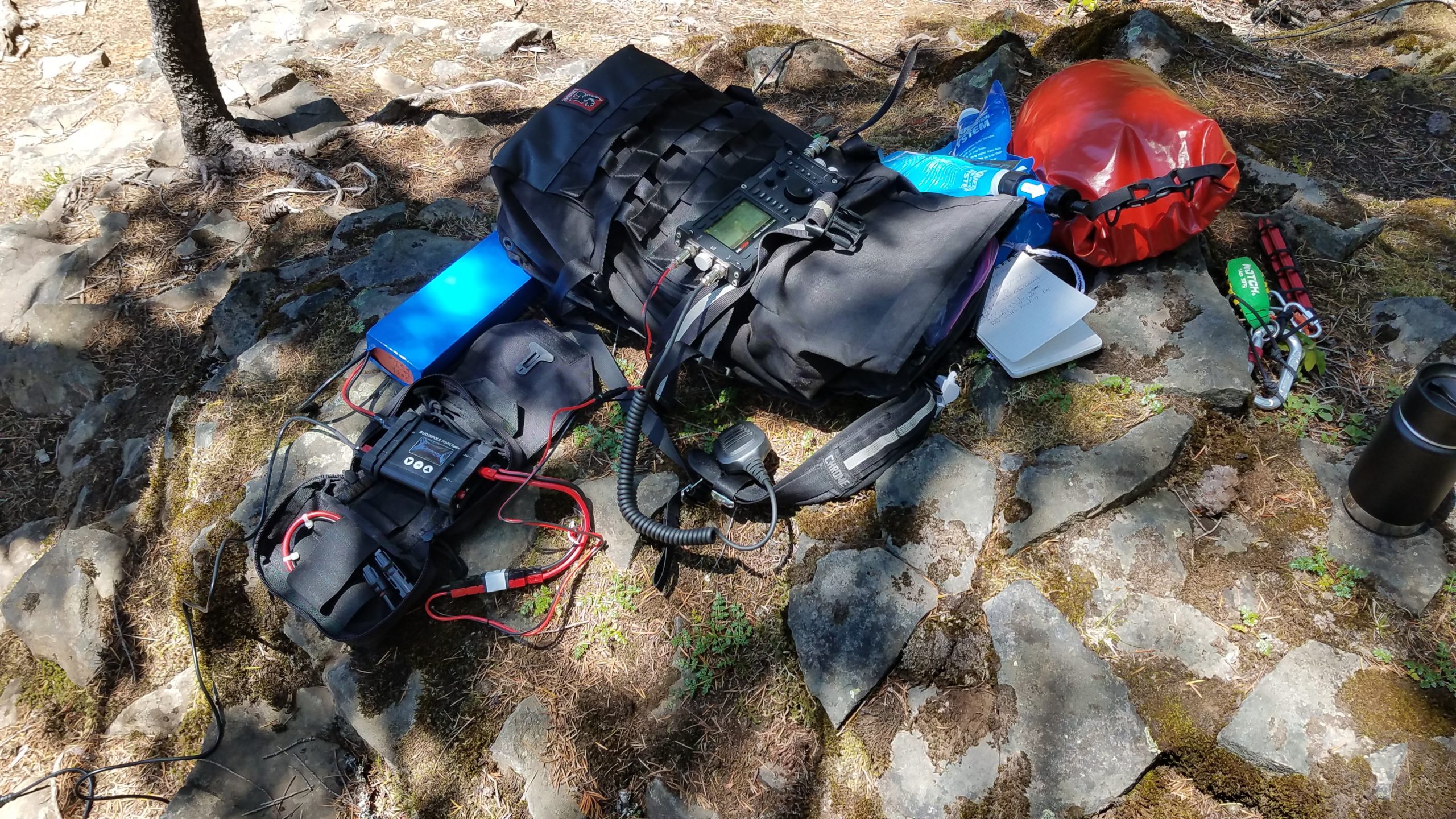
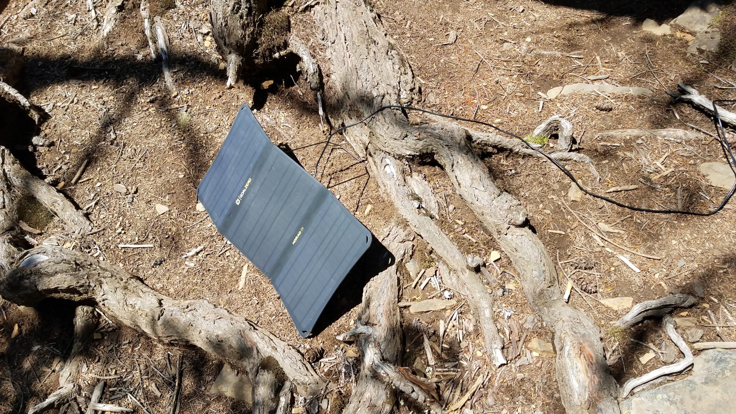
Radio station deployed in the shade and set up for voiceSolar panel keeping the station’s batteries charged
Bad photo of the transformer end of the Cha EMCOMM III suspended from the tree by paracord.
Bad photo of the other end of the antenna hanging from a tree suspended with paracord.
A video of the waterfall to make up for the bad pictures of the poorly-hung antenna
Lessons learned
It’s hard to photograph thin wire antennas in trees from the ground.
Don’t forget to take pictures when you mess up.
Better antenna placement yields better results. I didn’t properly assess the height of the hump relative to where the antenna was hung or account for the antenna sagging in the middle near the top of the hump.
Sometimes the space weather doesn’t cooperate and you can’t account for it.
Take all sorts of pictures when operating, especially in an interesting environment. I did some drive-by VHF Winlink work going through Eugene, OR and also did some HF work and SWL on the beach at Crescent Lake as well. None of that includes my improvised sun shelter made from part of a shelter tent and some branches sawed off of dead trees near the beach shored up with rocks.
A notable plus is that the 20W GoalZero Nomad 20 solar panel is enough to keep the radio station up and running doing both phone and data work in good and intermittent sunlight. I typically get 1A out of the panel in decent sunlight. The 12Ah Bioenno battery was fully recharged within minutes of the QRP radio transmitting both at Salt Creek Falls and Crescent Lake.
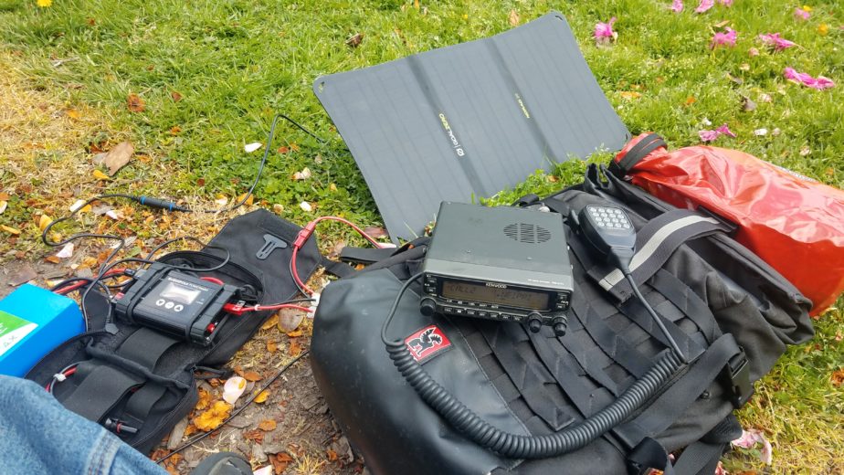
After a bit of a posting hiatus I thought I’d post a bit about some impromptu radio operation from a park on a fairly sunny weekend day. My partner had a meeting with some folks in our pod in Ladd’s Addition, a Portland neighborhood with a central park so I decided to set up my portable radio station and do some UHF/VHF work locally to see who I could reach from said park. The station I brought is based on a Kenwood TM-V71A and fits in a single bag along with a battery and a 20W folding solar panel. This is essentially the same setup I’d use for emergency communications with a larger antenna or solar panel.
Ed Fong roll up j-pole deployed in bushPortable UHF/VHF radio and power setup.
I ended up putting my modified Ed Fong DBJ-1 roll-up j-pole antenna in a large rose bush and hooking it up to my TM-V71A, and hooking the battery, solar panel, and charge controller up. I started operating at medium power (10W) and was able to reach Roger, W7RC, in Battleground, WA without issue on the 2M calling frequency (146.520MHz). This is pretty typical as he runs a beam antenna with the capability of transmitting at 1.5KW and is something of a local fixture. He reported me coming in with full quieting at 10W, and when I dropped to 5W (low power) he heard me with a little static. I also made some additional contacts including one in the Council Crest area: Ed, WB2QHS. He was out for a walk with an HT and we were able to talk with perfect clarity and then some static as he moved around with me running 5 and 10W. His elevated position helped facilitate communications. In about 2.5 hours I used somewhere around 1.3Ah of battery power, but was able to recharge the battery completely from the solar panel by the time I left. Not bad! The radio draws about 0.6A idling, and the solar panel charged at a maximum rate of ~1.1A in more intense sunlight. When I was transmitting at 10W the radio drew ~5A and at 5W ~3.5A. All these power figures are as measured by my Buddipole Power Mini. The current model features a USB port where the one I’m running doesn’t. I should also mention I topped up my phone charge from the battery as well.
If the solar panel provides more power than is required for the radio’s operation and the battery is charged the radio doesn’t draw from the battery. In the event the solar panel isn’t providing enough power to cover the radio’s power needs it dips into the battery, and when the radio consumes less power than the solar panel provides the battery is charged with spare current.
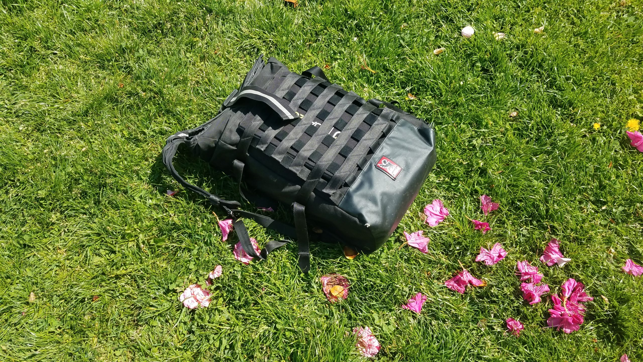
UHF/VHF setup packed up in a single backpack.
As shown above the whole station packs into my backpack without issue. Were I not on call for my job and carrying a hotspot and laptop there would be some additional room in the bag.
Portable radio station block diagram depicting the connections between various station components.