Estimating power consumption for your equipment

Hello everyone! Today I wanted to post about a topic that is pretty important if you have an interest in off grid, grid down, or emergency communications: estimating power consumption for your equipment. This post is in part inspired by a topic I chose for the Portland Neighborhood Emergency Team chat net. Shortly after I chose this topic I got an e-mail from Kevin, N6KVN asking for some advice for setting up a portable field station, and so I figured I’d write a more detailed post about my methodology and way of thinking about operating a ham radio station when grid power isn’t available from a preparation or pre-planning standpoint.

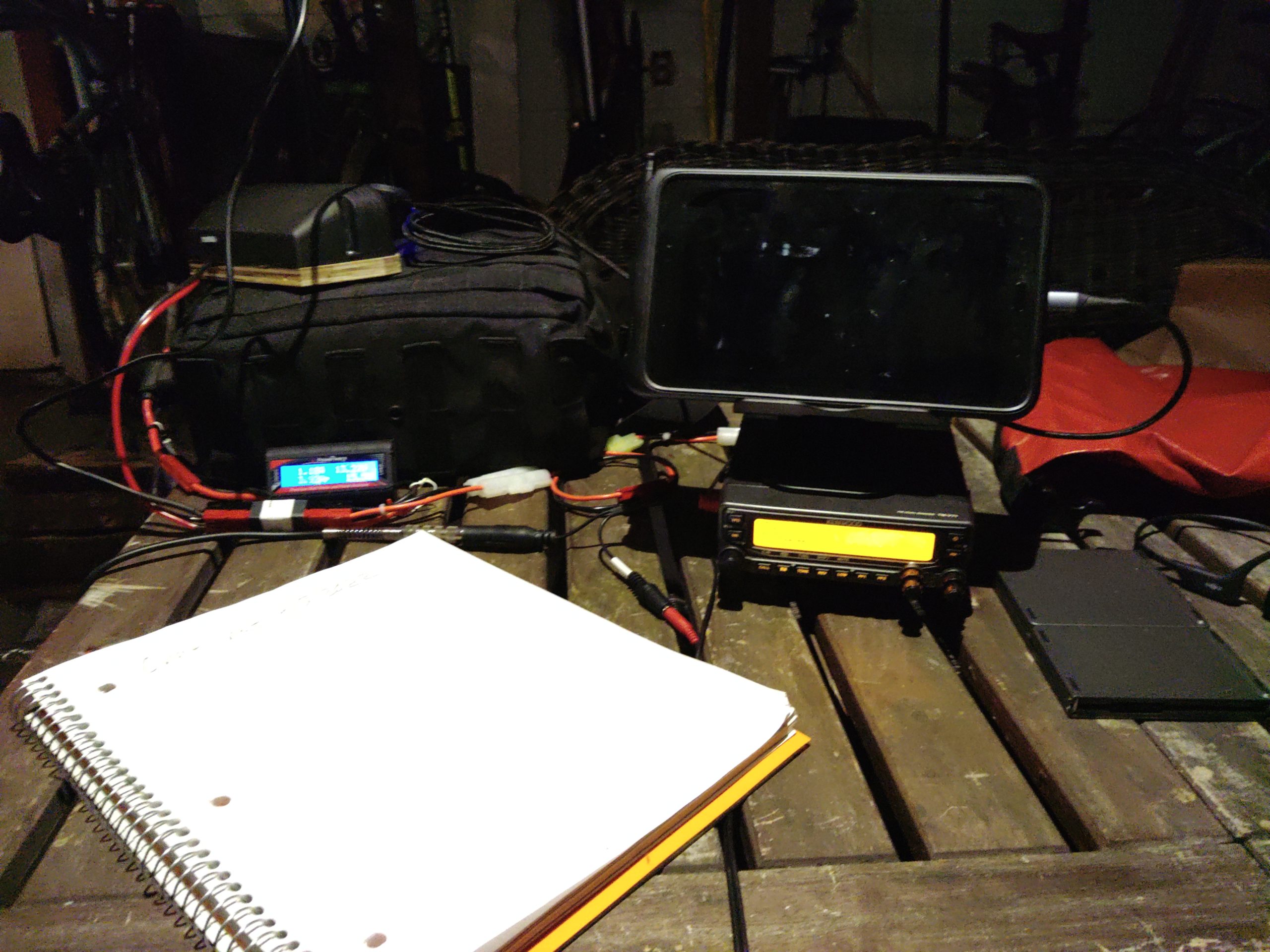
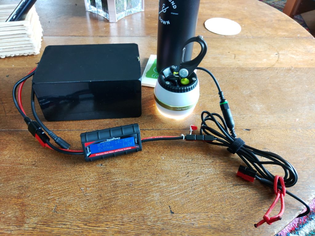
My basic test setup consists of three components. I have a power source of some kind. This could be a battery or a wall-connected power supply. The next component is a power meter connected between the load(s) and the battery. This component actually does the work of measuring power consumption. The final component of the test setup are the loads you wish to test. It’s important to make sure all the components in the setup are rated for the amount of current you expect to draw during testing. You can usually find that in the specifications of each individual component. You add those up and make sure your meter is rated for that much current and that your power supply can supply all of the required current. All the wiring in between should also be properly rated for that amount of current.

Example lighting current draw test
Example test setup

In this example I demonstrate testing a lighting device that runs on 12V and explain my methodology for hooking everything up and how I use back-of-the-napkin math to estimate power usage and requirements. In the above photo we have all three of our components for this specific test – a power source which is a battery in this case, the Powerwerx inline DC power meter, and load which is an LED lamp whose power usage I want to characterize. The Powerwerx inline meter supports a lot of measurements but in this post I’m going to mostly focus on current drawn and Ah, or amps per hour.
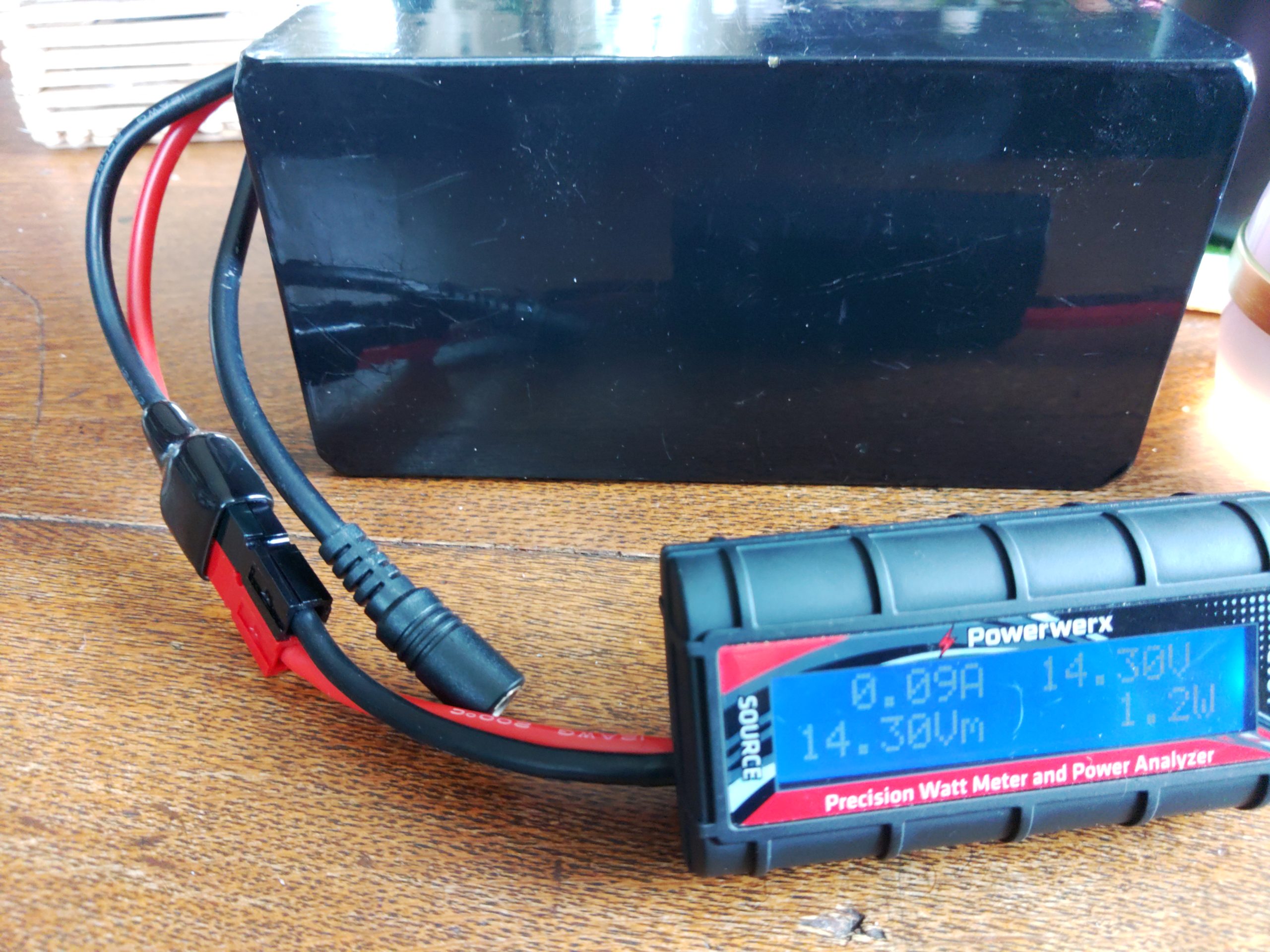
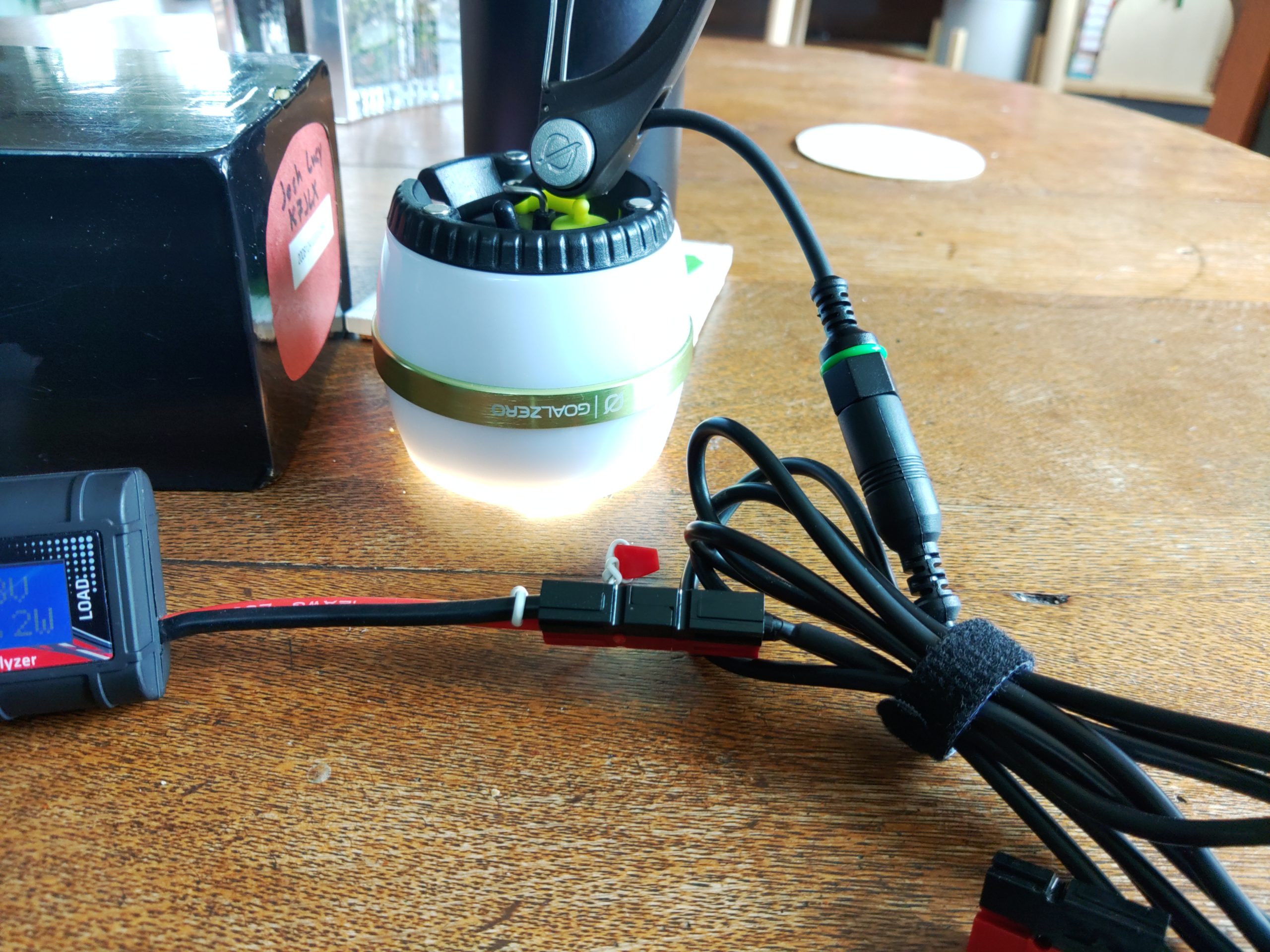
I started by connecting the power source to the “source” side of the power meter and then connected the load I wanted to test to the “load” side of the power meter. The images above show the light on but I will usually measure power with all the loads turned off to see if they draw current in the “off” position. It’s pretty common for devices to take a small amount of power even while off. This is called a parasitic load. The specific LED lamps I wanted to test have three settings: off, low, and high. I tested off and my power meter registered no current consumption. That’s probably because these lights have a hard off switch.
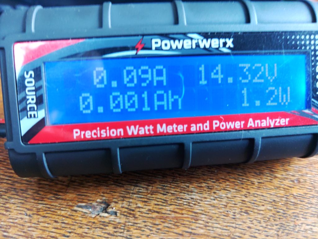
Power consumption with the switch in the “low” position

As you can see here this light draws 0.09A in the “low” position. If we were to run this device for 1 hour it would take 0.09Ah (amps per hour). You might have also noticed that there’s a measurement reading 0.001Ah. For this specific meter that means we’ve used 0.001Ah since the meter was connected to a load. There will be more on this measurement later.
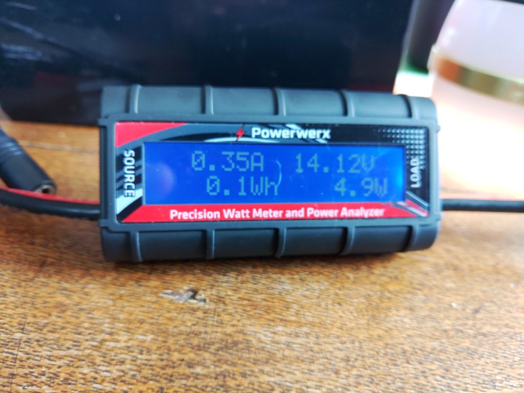
The LED lamp with the switch in the “high” position

With the LED lamp in the “high” position it’s drawing 0.35A of power. With the information gathered so far I can estimate how much power I’ll need if I want to run this light for a certain amount of time, and I can figure out how much power I can expect it to take while it’s running. If we use the Ah reading I mentioned earlier we can also understand how much battery capacity we’ve used since the last time the meter was restarted. Let’s start with that since I mentioned it.

To determine how much battery we’ve used as a percentage I’d use the following formulas:

battery capacity used as percentage = battery capacity / battery consumed

battery remaining as percentage = 100% – battery capacity used percentage

For a theoretical battery with 20AH of a capacity and 2Ah consumed the formula looks like:

20AH / 2Ah = 10% capacity used

100% – 10%= 90% capacity remaining

Now let’s add time to the mix. I’m going to use a Yaesu FTM-100D radio as an example of thinking about how much power it will use based on the specifications from the manual. According to its specifications when it’s receiving only it’ll draw 0.5A. The max power it will draw when transmitting 50W on 2m is 11A. Using this information let’s figure out how much battery we’d need to operate this radio some percentage of the time for 8 hours. For the purposes of this post we’ll call the amount of time we’re transmitting our duty cycle. We’ll assume we’ll be transmitting at 50W for 10% of the time that the radio is powered on. The formula will look like this:

Ah used = current * hours * duty cycle

While the radio is receiving only during an 8 hour operating period we’ll use 3.6Ah of battery capacity:

0.5A * 8h * .90 (90% receiving time) = 3.6 Ah capacity used

Now we should compute power usage when transmitting at 50W:

11A * 8h * .10 (10% transmitting time) = 8.8 Ah capacity used

Total power consumption over 8 hours for the radio:

3.6Ah (RX only) + 8.8Ah (TX at 50W) = 12.4Ah

When we add them up we need at least 12.4 AH of battery capacity to run that radio for 8 hours while transmitting 10% of the time. If you want to run the radio for 16 hours transmitting 10% of the time you’d either need to be able to re-charge that battery to replace the discharged power before the battery gets too low or have a battery large enough to run the radio for 16 hours, meaning you had at least 24.8 AH of battery capacity. There’s also a way to cheat on battery capacity. If you can reliably charge your battery as you run your radio from a source like a solar panel you can replace current that’s drawn down by your loads. In that case you’d just subtract the current you’re able to supply from your charging source from the load. If you end up with 0 or a negative amount of current draw you’re able to power your radio without discharging the battery.

Figuring out how much power you use as you go

This section can apply to both bench testing and operating in “the wild”. This details how you’d use any power meter that’s capable of measuring cumulative power use while you’re running loads. The Powerwerx meter I mentioned earlier and the BuddiPole PowerMini have this capability. If you connect one of these power meters inline with your setup as you operate and run loads it will add the cumulative power drawn. This can be useful when you want to understand how much power you’ve drawn down on a battery. As I write this before the 4/3/2022 Portland Neighborhood Emergency Team chat net and NET net I plan to operate on battery with lighting during the net and record my power usage here later, but the thing I do is the following for both bench testing and off grid measurements:

  • Connect my power meter between the power source and load as described above
  • Perform whatever activities I would normally perform
  • When done I check the consumed Ah on the meter to get my battery capacity used
  • Calculate battery percentage used

Formula for calculating battery capacity used:

battery capacity used / battery capacity = percentage capacity used

For an example with a 20AH battery and 15Ah of capacity used during some activity I would have 25% capacity remaining on the battery. I can use this formula in the lab to estimate how much power I’ll need in the field later, or understand how close I am to drawing my battery down in the field:

15Ah / 20AH = 75% used battery capacity

100% – 75% = 25% remaining battery capacity

Adding it all up

When you perform this kind of analysis on devices you expect to run off of battery in the field you can begin adding up all your field components and understanding what your power requirements will be. If you know your lighting will take 2Ah to run for a few hours at night and 12 hours of radio operation might cost 13.2Ah you can say your station will take 15.2Ah to operate for 12 hours. As you add more devices such as phone chargers, laptops, etc. your power requirements will change. You can also use this methodology to reduce power consumption. For example if running your radio at 5W is sufficient to achieve your communication goals you could save a lot of power, requiring a smaller battery, or less recharging capacity. You could also achieve similar results by having fewer devices or keeping your radio transmissions more brief (decreasing your duty cycle). Comparing the sums of power consumption between different setups can also help you inform either your expectations of how to operate or what is possible with the setup you have. It can also help you right-size a battery or recharging system for your specific uses.

A real-world example
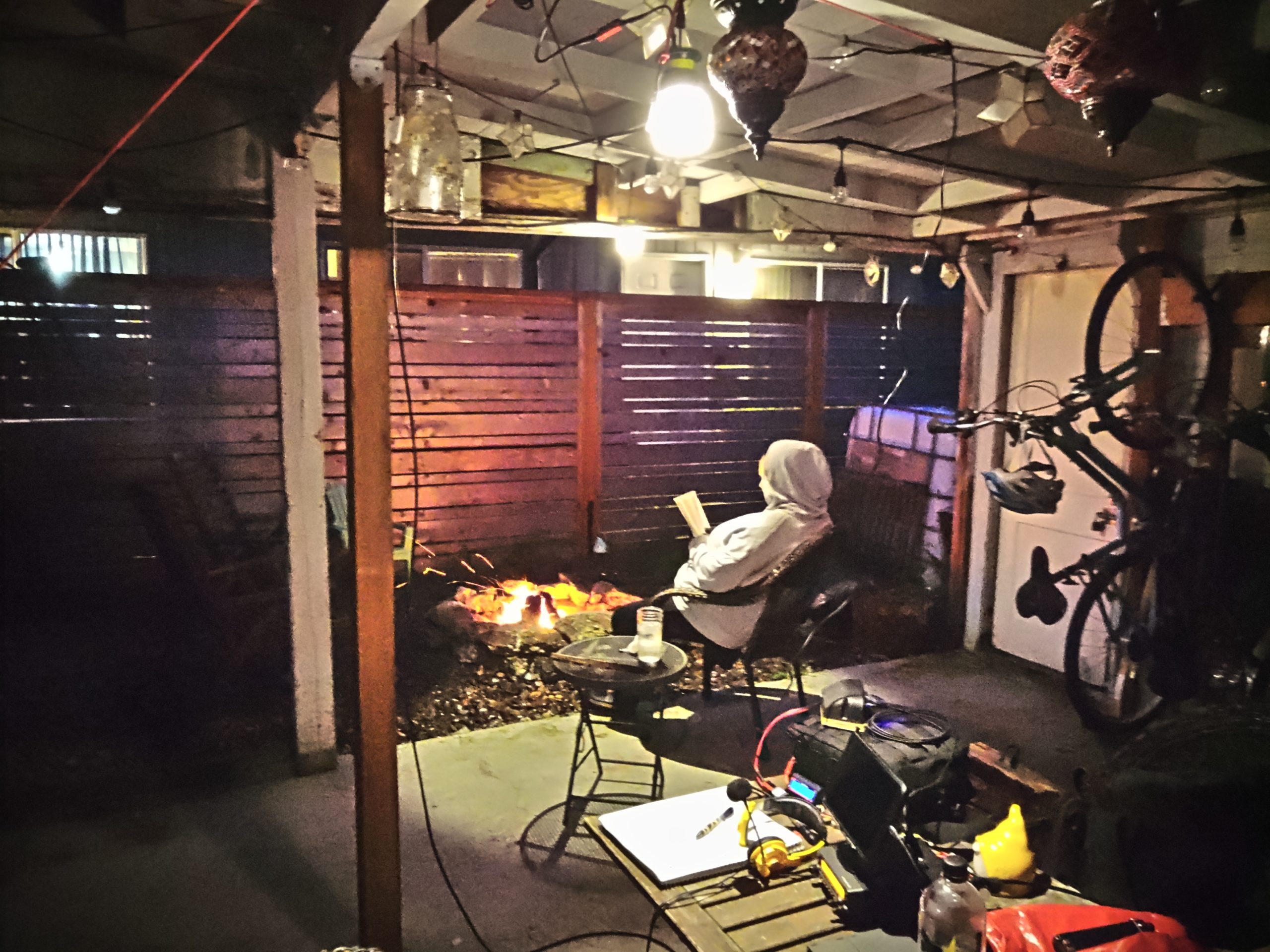
I wanted to add an update with another example of operating the radio in reasonable conditions doing a specific task that isn’t entirely theoretical, or just on-the-bench testing. Tonight I was net control for the Portland Neighborhood Emergency Team chat net, and I also participated in the Portland NET net as well. For most of the nets I was running two LED lights and I topped the last 25% of my tablet’s power off. I ran my Kenwood TM-V71A at 5w which drew about 3A when transmitting and 0.55A receiving. Both of the LED lights were set on low and consumed 0.1A apiece. The charger’s power usage varied depending on the part of the charging cycle the tablet was in, but at the end of 3 hours of running the radio, and about 2 hours of running both lights I used a total of 3.42AH of battery capacity. The battery I was using has a rated capacity of 40AH, so I used about 8.6% of its capacity (3.42AH used / 40AH of battery capacity = 0.086) doing both nets and listening on the first net’s frequency for an hour before it began. The first net that I was transmitting more on used the majority of the capacity, about 2.3AH. During the second net I only used about 1.1AH because I spent the vast majority of it listening as we ran lights and the tablet charger.

Tying it all together

By the end of this blog post I hope you came away with a good understanding of how I approach understanding and estimating my power usage and right-sizing my equipment for specific uses. This approach also helps inform how I operate when I don’t expect to have reliable power or when my situation changes and I’m not able to recharge batteries, etc. It can also show you how big of a difference it can make when you transmit less or when you add or drop devices from your setup.

This pattern can potentially be applied to other equipment like medical devices that can be run on battery. I’ve used the same method to profile my partner’s CPAP machine’s power consumption with various settings. I’ve been able to determine what sort of battery and charging system that will be required to keep it running when grid power fails or is unavailable (hint: turning off the humidifier and tube heater really saves a lot of power).

Notes after the fact

On the advice of Kevin, N6KVN I’m going to add a note about batteries. While this bit of the post is a bit out of scope it’s important to touch of the strengths and limitations of various battery technologies. Some batteries can be damaged by discharging them to 50% and others can be discharged to 20% or possibly lower before damage occurs. It’s important to understand the characteristics of the equipment you’re running. If you’ve read other posts of mine you’ll notice that I field a lot of LiFePO4 batteries. One of the reasons (apart from weight and other safety factors) that I tend to use them is because they can be discharged to a depth of 20% of remaining capacity before they’re permanently damaged. Most common lead-acid battery tech (think car batteries) can only be discharged to 50% before permanent damage to the cells occurs, but they are much cheaper than lithium batteries. Comparisons of various battery types is an entire post of its own, but these things are worth mentioning as you size your system and plan for the amount of energy you expect to discharge or plan to use. As an example my 100AH battery really has a usable capacity of 80AH because if I were to discharge the battery to 20%, or 20AH it would cause permanent damage to the battery (100AH capacity * 20% limit = 20AH, 100AH capacity – 20AH limit = 80AH of discharge before damage). This information should be listed by the battery manufacturer. If it’s not included I’d recommend reaching out to their support team.
Working ISS (01/23/2022)

This post is a bit of a quickie, but it covers an attempt to some of the basics about working ISS’ voice repeater and APRS digipeater. During this attempt to work ISS I wasn’t able to make any voice contacts, but I started with the following:

  • An Android phone running ISS Detector Pro
  • 5″ piece duct tape
  • Yaesu FT3DR
  • An Arrow handheld dual band 2m/70cm satellite antenna with built-in duplexer

Theory

As ISS or any satellite orbits earth in a non-geostationary orbit you’re likely to eventually have a certain number of passes over your location, depending on how the satellite is orbiting. You can use software to predict orbits, and therefore you can be ready when the satellite passes overhead. Ideally you’ll have the transponder frequencies of the satellite you’re trying to reach pre-programmed into your radio along with some doppler-shifted frequencies to try to reach the satellite as it approaches and departs. I didn’t do that, but have had decent luck without the doppler-shifted frequencies. Passes typically last minutes. What’s happening is that a lot of satellites have an uplink (ground -> space) and downlink (space-ground) frequency. Your radio must be able to transmit on one and listen to the other to make contacts. There are some cases where that’s not necessary such as working satellites with APRS digipeaters, or just receiving signals.

The attempt

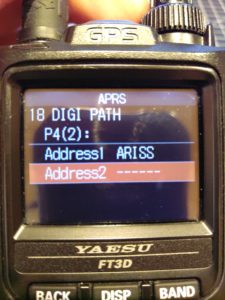
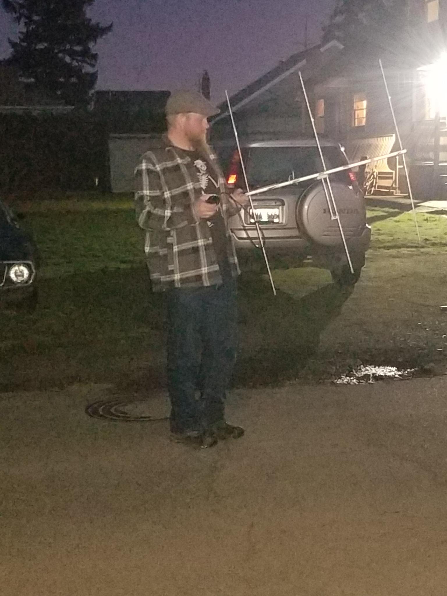
I used the ISS detector pro app to find a longer pass (this one was about 6 minutes long). Before the pass I set my antenna up, connected it to my radio, and made sure it was in working order. After that I taped the phone to the beam of the antenna between the first 2m elements where it would fit using a piece of duct tape folded in on itself. Taping the phone to the boom enables me to aim the antenna using the app (screenshot later). I also configured the frequencies for the APRS digipeater on ISS, the crew communication uplink and downlink frequencies, and the FM repeater frequencies. As a side note sometimes astronauts, who are also licensed ham radio operators, will man the radios and talk with folks on the ground. In addition to programming frequencies you need to also program your APRS radio to use the digipeater path ARISS, otherwise the digipeater won’t send your packets back down to other stations.

Yaesu FT3D radio's APRS path configured to be "ARISS".
Yaesu FT3DR digi path set to ARISS or ISS.

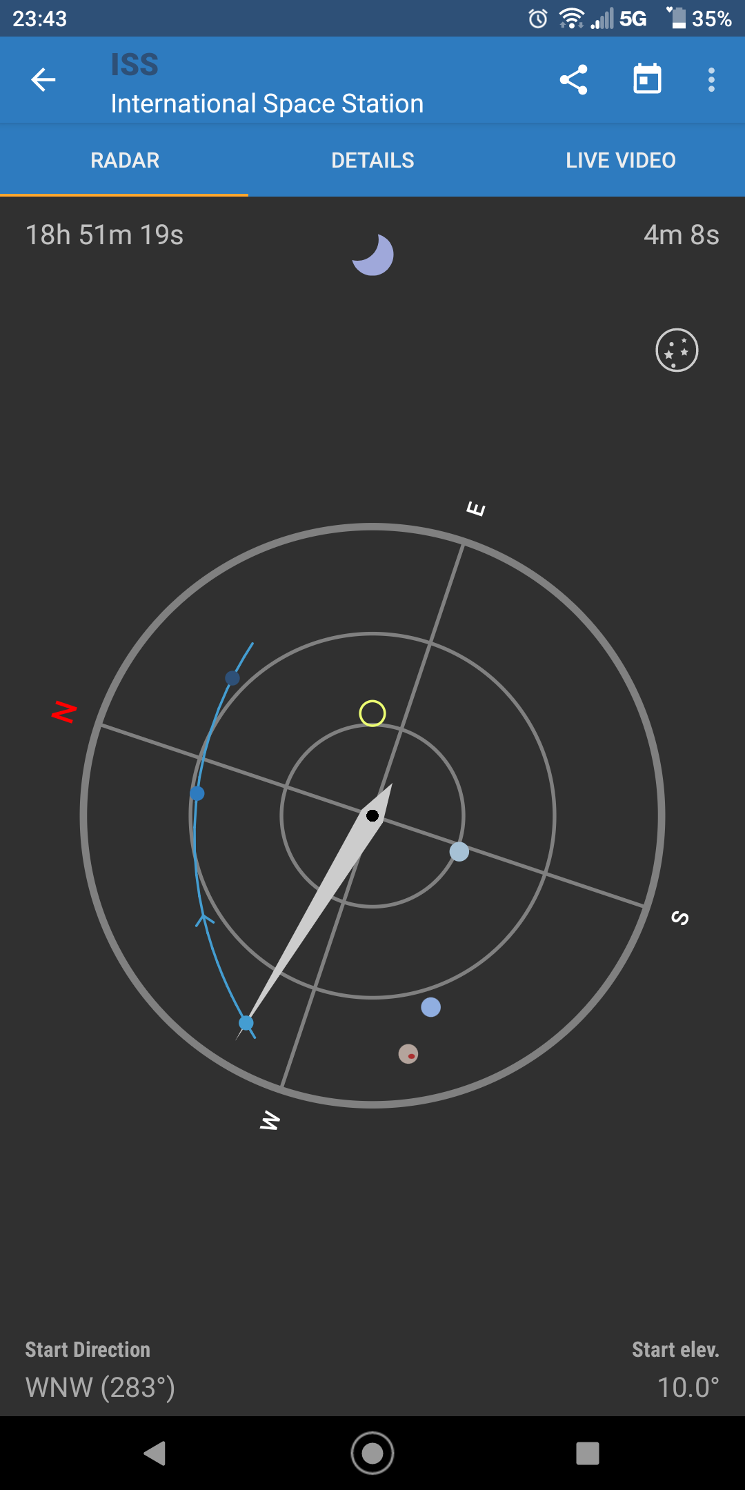
Now it’s time for action! There’s a very narrow window to hit the ISS, so there’s a need to be quick and prepared. I went out in the street near my house a few minutes early with a clear-ish view of the sky and aimed the antenna at the satellite using the app. A screenshot below shows what the aiming screen looks like. The yellow circle is the direction the top of your phone is pointing and that should be aligned with the satellite on its track, the blue line with dots. The center of the screen is up and the and the outer ring is down. As the satellite passed I just aimed the antenna with the aid of the phone and tried to use the repeater. I didn’t hear anyone, but was able to switch to APRS and sent a beacon. I saw that the packet I sent was digipeated by ISS! Following that I checked the ARISS page and saw my call sign! You can also check https://aprs.fi and see your location as well as the path by which your packet arrived. The first hop for my position report was the ISS.

aprs.fi screenshot showing a path via NA1SS
An aprs.fi screenshot showing a path digipeated by NA1SS before going to APRS-IS via KM6YLW-2.

100Ah battery box build

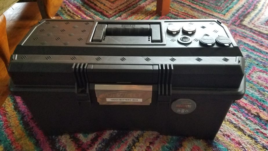
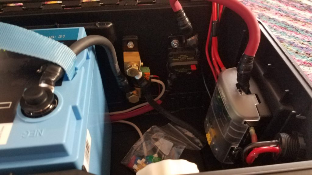
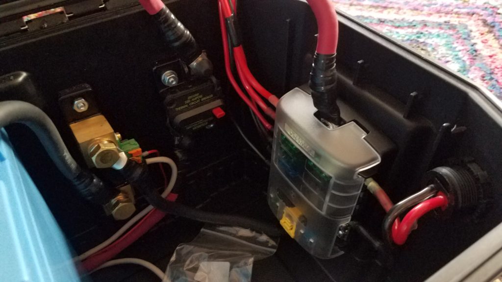
Ok, so this is a big one. I wanted to build a battery box that could keep me going a few days without being able to charge while camping and/or operating. I also wanted accurate power accounting and the ability to understand my power consumption and have alarms when usage exceeds specified thresholds, providing the opportunity to either adjust usage or in an emergency not be surprised when I drop out. I also wanted to design the system for maximum flexibility when it comes to charging and connecting loads. Most commercially-available systems that met capacity and power needs were designed around inverters and larger 30+ volt solar panels that were designed to mount on structures or large vehicles like RVs or vans rather than the smaller and more portable 18v open circuit foldable panels that are used more commonly for my purposes. Having a wider range of panels that I can use is better because it would be good to charge from either so not building in charging was ideal. I also found the options for high-amperage DC connectors lacking in many pre-built options. Some units would have one or two 25A outputs, but those are at the max current range some of my radios will draw at full power. I wanted some breathing room current-wise. In the event I wanted to operate one of my bigger radios at full power I’d rather not risk burning a fuse out or damaging my power source – especially in the field while I’m relying on it. It’s also nice to have many connectors available on the source which eliminates the need for a bunch of splitters. None of the commercially-available options I evaluated provided more than two high amperage connectors. Finally, I wanted a couple USB fast chargers for my and my partner’s devices which many commercial options provided, but they’d typically provide a single fast charging port.

I took some inspiration from a Powerwerx box that a fellow ham and NET team member Laura, KI7ZZQ purchased. That battery box was designed to accommodate a 50-70Ah battery which wouldn’t physically fit any of the 100Ah batteries I had been considering during the design phase, but it provided me a rough template I could build from in terms of layout. As with that box just including power distribution and monitoring in the box was a way I could reuse existing systems I have that perform well without having to buy more of those components. Buying a bunch of new parts is pretty expensive so not including more core devices in the box is definitely a plus.

This was not a cheap project, but I think it’ll be worth it.

Theory and design

By selecting a 100Ah battery I get 80Ah of usable power from the system without significantly decreasing the battery’s lifecycle. Using LiFePO4 batteries instead of lead-acid means I get an additional 30% depth of discharge without the destructive effects of discharging to 50%… The LiFePO4 battery I selected also weighs 26lbs. A similar capacity lead acid battery would weigh a lot more and probably require a much sturdier and expensive enclosure. Another advantage of LiFePO4 batteries is the lack of battery memory – that is to say the useful lifetime of a battery isn’t diminished by leaving it in a partially-charged state. Some battery technologies suffer from that problem which is a problem if you’re in a situation where you might not be able to completely recharge the battery completely during use. As far as parts go I wanted to attempt to source the parts I didn’t already have from a variety of vendors… I had a preference for smaller and more local vendors, but that didn’t work out 100% of the time. The enclosure (tool box) and a 1 1/8″ hole saw are two examples of where that didn’t work. The bill of materials will list the source of each component.

So let’s start with the system design itself. There are a few core components that I knew I’d probably want from designing a bigger high amperage system when my partner were considering purchasing and building out a van for camping/touring. The core parts that everything else would be designed around are:

  • 100Ah LiFePO4 battery
  • Reliable battery state and power usage monitoring capability
  • Battery disconnect for safety and preventing parasitic loads from draining the battery
  • Circuit breaker for the battery to prevent damage to components or fires
  • DC subpanel to split out and protect branch circuits
  • Two switched USB rapid chargers.
  • Flexible charging – AC-to-DC chargers (wall socket, generator), solar panels of various types, and DC-to-DC (vehicle, independent DC power supply, DC generator outputs)

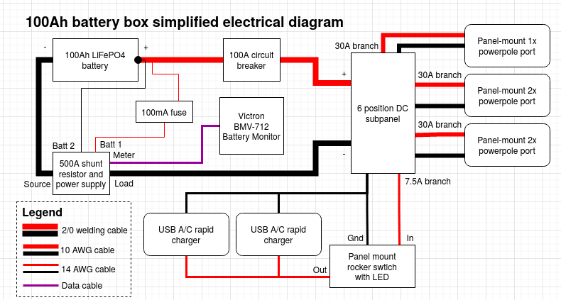
Those components are roughly connected and arranged as follows. Chargers can be connected to any of the powerpole connectors listed below, and so can loads. The only loads that wouldn’t be connected to powerpole connectors are devices directly connected to the built-in USB A/C rapid chargers. You’ll notice there’s a power line running from the battery to the 500A shunt resistor and power supply that feeds the Victron BMV-712 through a 100mA fuse, bypassing the circuit breaker which also doubles as a battery disconnect. That’s intentional as the BMV-712 requires constant power to track battery state and if powered off it will lose its zero-point configuration. This is the only parasitic load that isn’t switched in this system apart from the BMS built into the battery, but it’s required to get accurate battery status so I compromised.

Block diagram showing electrical connections between a battery, shunt resistor, circuit breaker, DC subpanel, USB chargers, and power connectors.

Materials / parts

High amperage and distribution components
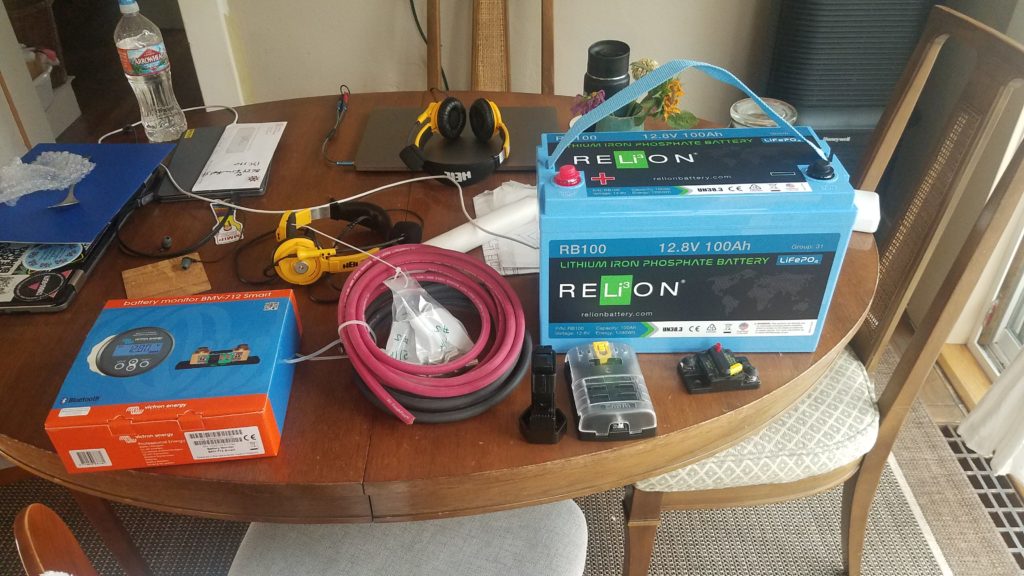
DescriptionQtyMake and modelVendorLinkNotesTool?
100Ah LiFePO4 battery1Relion RB100LightHarvest SolarHereN
Red #2/0 welding cable, 10′1?HereN
Black #2/0 welding cable, 10′1?N
100 amp circuit breaker *****1Eaton 285100FHereN
6-position 100A DC subpanel1BlueSea 5025HereN
Hammer-type crimping tool1TE(?)HereY
Battery monitor1Victron Energy BMV-712HereN
#2/0 Lug Ring Terminal (5/16″) *3?HereN
#2/0 Lug Ring Terminal (3/8″) *3?N
#2/0 Lug Ring Terminal (1/4″) *5?N
10A LiFePO4 14.6v battery charger1Bioenno Power BPC-1510ABioenno PowerHereDedicated AC-to-DC chargerN
Tool box1Dewalt DWST24082 One Touch Tool Box, BlackHome DepotHereUsed as enclosureN
#10-24 3/4″ cap screws and nuts (x8?)1?HereN
#10-24 1″ cap screws and nuts (x6?)1?HereN
#10-24 Bonded neoprene washer (x4)3?HereN
1 1/8″ hole saw1?HereUsed for Powerwerx panel mount devicesY
Panel mount powerpole socket (x2)2Powerwerx PanelPole2PowerwerxHereN
Panel mount powerpole socket (x1)1Powerwerx PanelPole1HereN
USB A QC + USB C PD charger, panel mount2Powerwerx PanelQCUSBCHereN
Bonded 10GA stranded copper wire, 25′1Powerwerx Wire-RB-10-25HereUsed for 30A branch circuitsN
Bonded 14GA stranded copper wire, 25′1Powerwerx Wire-RB-14-25Used for 15A branch circuitN
Powerpole to “cigarette lighter” adapter1Powerwerx SOC-PPHereStored in the enclosure as an adapterN
4-Way powerpole splitter2West Mountain Radio PWRNodeHam Radio OutletHereUsed as splitters for the 2x panel mount powerpole socketsN
Panel mount rocker switch w/red LED, 15A max1Powerwerx PanelSW-RedHereN
15/30/45A red powerpole housings6Powerwerx PowerpoleCaseHereN
15/30/45A black powerpole housings6N
Powerpole retention clips6N
45A powerpole contacts22N
Powerpole crimper1Powerwerx TRICrimpHereY
F2 blade connectors, 12-10GA3???N
F2 blade connectors, 16-14GA4???N
Lug ring terminal, 12-10GA6???N
Lug ring terminal, 16-14GA2???N
7.5A ATC blade fuse *3???N
30A ATC blade fuse *5???N
Assorted ATC blade fuses6???Included in enclosureN
Packing foam **????N
Electrical tape ***1???N
1 1/4″ bolt and flange nut ****1???N
Zip ties5???N
3/16″ (?) drill bit 1???Used to drill holes in plastic fins in toolbox for zip tiesN
Electric drill1???Used w/hole saws and drill bitsY
2″ hole saw1???Used to drill a hole for the Victron BMV-712 panelY
Phillips screw driver1???Y
Metal shears1???Used to cut #2/0 welding cableY
Diagonal cutters1???Y
Socket wrench1???Y
?mm socket1???Used for shunt boltsY
?mm socket1???Used for battery terminal boltsY
?mm socket1???Used for #10 nutsY
?mm socket1???Used for DC subpanel 100A contacts
Needle nose pliers1???Used to help pull wires, tighten panel mount nutsY
Claw hammer1???Used w/ the TE hammer-type crimping toolY
Pocket knife ******1???Y

Legend
? Can’t remember/unknown
— Same as above
* Includes spare(s) or extra(s)
** This is small-cell plastic foam used as packing to keep the battery from moving around a lot
*** Used mostly to bind wires and as extra insulation on the #2/0 ring terminals. Also used to physically shore connections up due to gaps in wire jacketing or potential stress points from bends.
**** Used as insurance to hold the toolbox closed in case the latch is opened unintentionally
***** Doubles as a battery disconnect switch
****** Used to clean plastic burrs left from the hole saws and to cut the jacketing on the #2/0 cable in preparation for crimping

Assembly

This was done in a a couple phases – in part because I was waiting for things to come in the mail, and in part because I sort of “winged it” building this out in terms of mounting components to the enclosure. The first thing I did was pick locations for each of the high amperage components: the battery, BMV-712’s 500A shunt, 100A circuit breaker, and the DC subpanel. I made sure to allow for enough space to run cables to and from each component before drilling holes for them. The battery was pushed to the left side of the tool box. This makes it a bit awkward to carry but creates enough space in the right side to mount everything.

Once I found a good placement for the components that required mounting I just drilled holes in the enclosure using the components as a template. For each component I drilled an initial hole and inserted one of the #10-24 cap screws in the hole to hold it. I then drilled out a second mount and placed another bolt in it. After I’d placed all the components and got the holes drilled for them I added the #10 bonded washers with the neoprene side on the outside of the enclosure. To minimize jagged edges from threads on the outside of the enclosure I put the phillips end of the cap screws on the outside as well. The nuts and lock washers were placed on the inside.

The next step was to route, measure, and cut the high amperage #2/0 welding cable between each component. I did a dry run of the cable from component to component and cut each piece to length. I ran a piece of from the negative battery post bolt to the BMV-712 shunt battery terminal, cut it, ran another piece from the shunt to the negative terminal of the DC subpanel to the BMV-712 shunt load terminal, and cut it. I then took the red #2/0 welding cable and ran it from the positive terminal on the DC subpanel to the 100A circuit breaker, cut it, and then ran another piece from the circuit breaker to the positive battery terminal, and then cut it.

For each piece of #2/0 welding cable I cut I stripped enough jacketing off of the end to fix the appropriate #2/0 lug ring terminal to the wire. Make sure the hole on each lug ring terminal matches the post you’re planning to connect it to. It’s worth double-checking before you crimp since each section of wire is cut to length. After verifying that I was using the right ring terminal for each connection I crimped them to the #2/0 welding cable. I then wrapped the bare metal parts of the lugs that might be prone to shorting with electrical tape since I didn’t have any heat shrink tubing. I also used the tape to shore the joint between the jacketing of the welding cable and crimp-on connector.

The next step is to hook the high amperage wire up to each component. This will help us figure out where to run the legs from the DC subpanel and to help us properly place the panel mount components without interfering with the high amperage wire runs and components mounted inside the enclosure. Before making the connections between components verify the polarity of the connections and break the circuit by pressing the reset button on the circuit breaker. The connections should be made according the the simplified wiring diagram above.

Completed mounting of all components in the lower portion of the enclosure

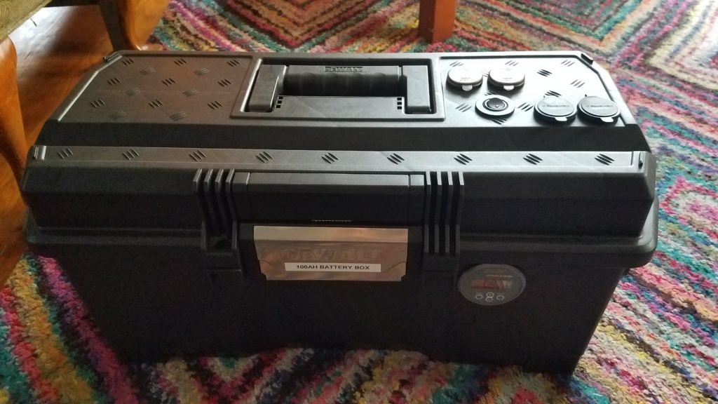
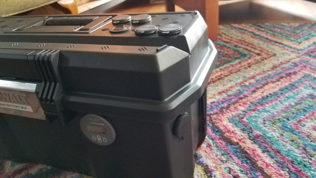
The next step is to place and mark each panel mount component. I chose to mount the BMV-712’s meter on the front of the tool box to the right of the latch since I mounted the DC subpanel on the flat part of right end of the toolbox. I mounted the 1x powerpole panel mount component on one of the angled surfaces on the right end of the enclosure so I could connect a charger easily when it’s stored on a shelf. I picked spots for the panel mount components on the lid because I think that’s going to be the easiest spot to make connections in the field. All the panel mount components were placed in such a way that the panel mount nuts cleared the plastic “fins” on the inside of the enclosure. Special care should be taken when placing components in the lid. There are a lot of plastic fins on the inside of the lid. Use the 2″ hole saw to cut the hole for the Victron BMV-712’s meter, and for all the other Powerwerx panel mount components use the 1 1/8″ hole saw. You might need to shave the decorative raised lines on the lid down with a pocket knife to ensure that the panel mount components mate to the outside of the lid properly.

Photo showing placement of all panel mount components

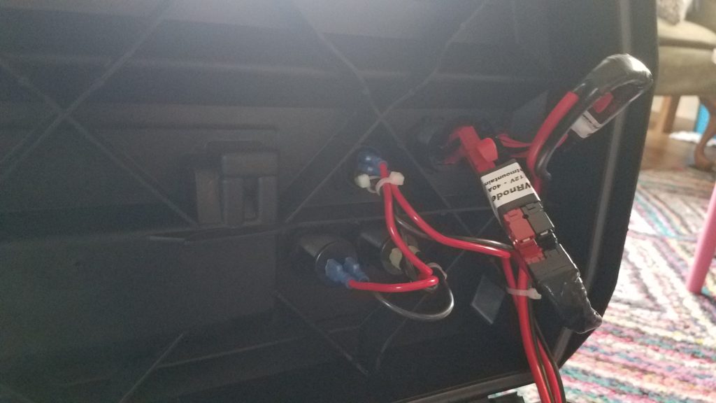
At this point it’s time to start making the connections from the subpanel to the panel mount powerpole connectors. Since I used 10GA wire capable of handling 30A it’s hard to daisy chain between ports so I opted to use some PWRNode splitters to make the connections to the 2x panel mount powerpole sockets. I made some shorter 2″ stubs of 10GA wire and crimped 45A powerpole conductors on both ends of each stub. Connecting all 4 ports requires 8 2″ stubs. Once I crimped the 45A conductors on I added the powerpole housings to one side of each stub. The other side of the stub was inserted into the panel mount connector. Each panel mount socket is connected to a single run of cable from the DC subpanel with powerpole connectors on the end of it. The idea is that each socket can support up to 30A of total current draw. Once that was complete the side with the housings were connected to the PWRNodes and powerpole retention clips were installed to keep all the powerpole connectors in place. The 1x powerpole connector was run directly to the DC subpanel. Each leg was then fused in the DC subpanel with a 30A fuse. I used some electrical tape to support the “joints” between the powerpole connectors that lead to the DC subpanel and the powerpole connectors themselves.

The next step in wiring the system is to connect the panel mount chargers in parallel and switch them with the rocker switch using the 14GA wire. This is accomplished using the connections as detailed in the simplified electrical diagram. The brass connector on the switch connects to the ground, the middle connector connects to the DC subpanel, and the silver connection on the end connects to the USB chargers wired in parallel. The photo below details how the connections to the panel mounted devices and sockets. I drilled a hole in one of the fins on the lid of the toolbox and wire tied the wires coming from the DC subpanel to the lid to keep the wires from migrating a lot during transport. I also used wire ties to hold some of the wires together coming out of the individual parts.

Now that all those connections are complete we can re-connect the battery, and while we’re at that we’ll hook the BMV-712 up. The BMV-712’s box has a handy connection diagram. In this step we’ll connect the battery and the BMV-712. First connect the BMV-712’s red (positive) wire connected to the temperature sensor lug to the battery using the ring terminal along with the terminal on the #2/0 welding cable. Both should connect directly to the positive battery terminal. Take care not to short the pin end of the BMV-712’s red power cable while connecting it. Once that’s connected to the positive battery terminal connect it to the B1 pin on the BMV-712’s shunt, and connect the black temperature monitor cable to B2 on the BMV-712’s shunt. The BMV-712’s manual will detail how that connection should be made. Now connect the gray 6-pin modular data cable from the shunt to the BMV-712’s panel mount meter. Once that’s been hooked up you can connect the negative battery terminal to the black wire leading to the battery side of the BMV-712 shunt. When properly connected the panel should light up blue and the display should become active. [Note: this was updated to include directions to connect a BMV-712 temperature sensor.]
Once all these connections are made and the battery is re-installed make sure you install a 7.5A fuse in the subpanel on the leg that connects to the USB chargers. If the 7.5A fuse blows during testing one or both of the USB chargers are wired backward. Use the + and – on the bottom to properly wire the positive and negative sides of the charger. Install 30A fuses on each leg that leads to powerpole panel mount sockets.

Now we’ll pull the yellow reset bar on the breaker back in to energize the DC subpanel. Once the subpanel is energized we can test the USB charger leg of the circuit by activating the toggle switch. The red LED should activate on the toggle switch, and both USB chargers should show their voltage with blue numerical LED displays. If all three of those work that’s wired correctly.

As a bonus I added some scraps of plastic closed cell packing “foam” around the battery to dampen vibration and shock to help hold the battery in place.

The installation is complete we can move onto programming the Victron BMV-712.

Configuring the Victron BMV-712

At this point we should set up the battery monitor. Some of the instructions in this section come in part from instructions provided to me by LightHarvest Solar. I modified some of the values in the configuration to better fit my use-case. The instructions in this section assume you’ve charged the battery completely using an appropriate LiFePO4 battery charger. I used the Bioenno charger listed in the bill of materials to fully charge the battery before configuring the BMV-712. To begin you’ll want to install the VictronConnect app on a device that it supports which also has Bluetooth. There are versions for IOS and Android.

After opening the app you’ll want to select your BMV-712 and pair with it. I also recommend changing the BMV-712’s pin to make sure someone doesn’t pair with it and modify its settings, especially if you’re around RVs or others with a Victron battery monitor. You can then modify the settings on the device. The major configuration tasks to do are configuring the parameters for your battery and doing a zero-point reset once your battery has been fully charged. To begin with we’ll configure the battery monitor with the properties of the Relion RB100. You can leave all the settings as defaults unless they’re specified below. I got the initial values and instructions to configure the battery monitor from LightHarvest Solar. It was provided with the purchase of the BMV-712. After opening settings and choosing “Battery” set the following:

  • Battery capacity: 100Ah (this is a 100Ah battery)
  • Charged voltage: 13.9V
  • Discharge floor: 20% (This is the lowest capacity you want the battery at)
  • Peukert exponent: 1.00
  • Charge efficiency factor: 99%
  • Current threshold: 0.10A
  • Time-to-go averaging period

Optionally, you can configure alarms for the system. I turned on the alarm buzzer and set the “Low SOC alarm” to go off at 40% and clear at 45%. Since you don’t want to draw the battery down lower than 20% I picked 40% to give me a warning well before I draw it down. If you draw the battery down below the discharge floor it can be damaged. You can also optionally configure a temperature alarm if you have the BMV-712 battery temperature sensor. See the “updates” section at the bottom of this post for details.

Once the battery has been configured and ALL loads and chargers except the BMV-712 have been disconnected you can then click the “synchronize” button, and then click “calibration”. Synchronize sets the battery state-of-charge to 100%. Calibration zeroes out the current measurement on the shunt resistor. If you disconnect the battery monitor you’ll need to redo this part of the process starting with a full charge.

Using the BMV-712

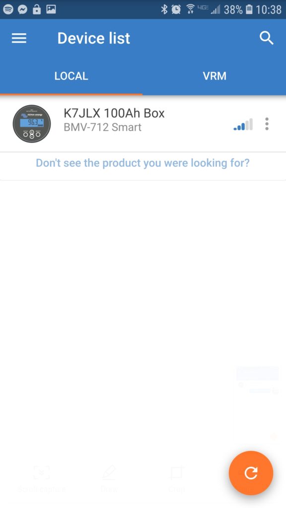
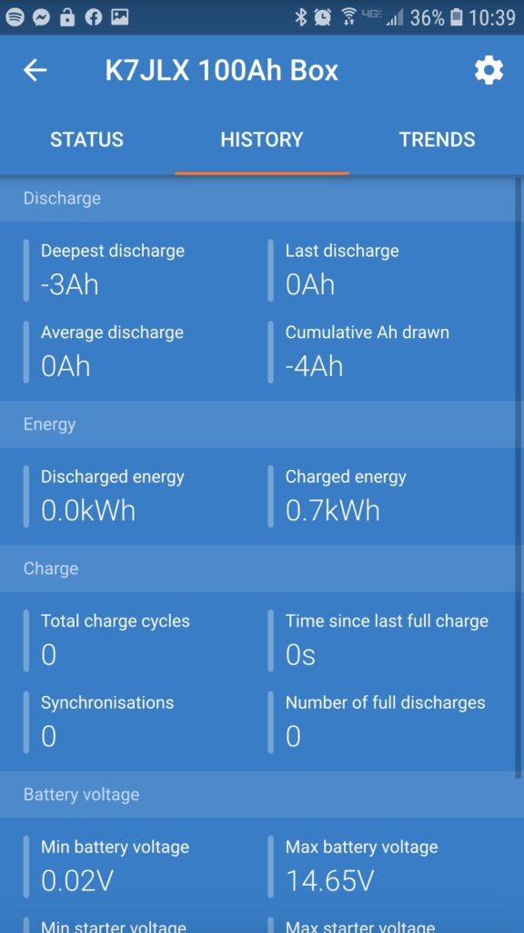
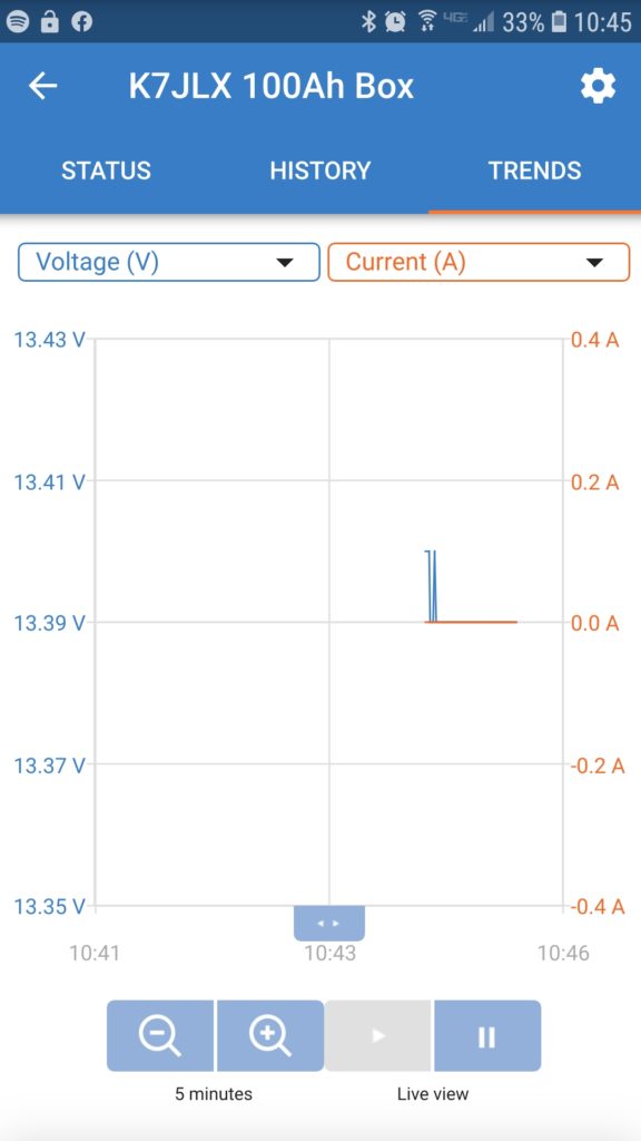
While this post is mostly focused on the app the display panel on the BMV-712 can display the status information using the arrow keys on the front panel. Navigating that is pretty easy, but I’d also recommend reading the manual as there’s more to the panel than just displaying data. The most common screens I use in the app are the device list which is used to manage Victron devices. They have an entire ecosystem of devices that can be managed and monitored from this app. I go through this to connect to my battery box. The battery box has been renamed in the settings (gear icon seen in the other screens). The status page shows you all the current stats for your battery – state of charge, voltage levels, current, and power. There’s one thing that’s cut off at the bottom which is the status of the control panel’s relays. For my configuration the relay is open since it’s not really doing anything. The history tab shows you stats for your battery over time. This data can be cleared, but it’s nice to understand what you’ve done with your battery over time so I probably won’t be clearing that until I replace the battery in the system. The trends tab is really nice to use when you’re watching your battery in real time from within the app. You don’t get data points when your app isn’t connected unless you get a Victron Cerbro GX or similar device but that’s overkill for my use-case.

Problems left to solve

There are still some problems to solve. I need to install some sort of barrier that prevents the battery from moving to the right inside the enclosure. I’m thinking about bolting a barrier into the enclosure to prevent too much movement. The toggle switch on the top isn’t weather resistant either. The toggle switch comes with a plastic cover but it’s impossible to install without the rocker switch popping out of the panel mount.

Updates

I decided to add a temperature sensor to the BMV-712 in order to make sure I’d get an alarm if the battery was out of the appropriate range to charge which is a more narrow range than the discharging temperature. The changes I made to connect the battery temperature sensor was to purchase a temperature sensor for $25. I disconnected the old wire running from the positive battery terminal to the current shunt, connected the new one, and connected the new larger lug to the battery terminal. I then connected the black wire for the temperature sensor to the open input on the shunt. After that I configured the BMV-712 to use the second input as a temperature sensor using the web application. Then I configured my high temperature trip temp to 55C and the high temperature clear to 53C. The alarm will go off 5C before the battery’s charge limit of 60C. The low temperature alarm was set to -15C and the low temperature clear was set to -13C. -15C is 5C above the battery’s minimum charging temperature limit of -20C. The connection diagram has been updated to reflect the new temperature sensor connection. This post talks about recently implemented changes to the battery box.

Coping with the heat wave

Hello all, while this isn’t actually a post about amateur radio I wanted to post about how we (my partner and I) decided to deal with the June 2021 heatwave in the Pacific Northwest. While this isn’t directly related to ham radio I think it’s worth discussing as the temperatures in this region don’t typically reach the levels they were at and most homes and people aren’t prepared to cope with those temperatures. Some folks will probably laugh at this post and the situation in its entirety, but you have to remember that homes, businesses, animals, and people in what is typically a fairly temperate climate aren’t used to these sorts of temperature spikes. Some of us will mostly be uncomfortable and maybe inconvenienced but for others this is a deadly situation. There are large numbers of unhoused folks sleeping rough and stuck outdoors during this time. It is easy to die of exposure in situations like this even in a city. In nature you might be better or worse off depending on where you are. When operating in the field it’s important to keep yourself and your equipment cool, and I don’t think this is the last time we will have unseasonably hot weather. Next time it could be during another disaster or trigger secondary problems like power outages. This post is mostly about optimizing a solution for a problem with cheap and easily available materials to decrease misery and help alleviate a situation that could lead to an emergency.

One obvious issue with the house we live in during this specific situation is that it has a very large single-paned south-facing window, which definitely heats the house up during the summer. We were fortunate enough to have a single window-mounted AC unit for the whole house but it was only able to keep the house in the high 80s to low 90s which is definitely better than 110+ degrees, but I wasn’t sure if the power grid would hold up under additional load and the heat itself. My partner and I decided we’d take some steps to cool the house further for our comfort and our dog’s safety. The most obvious thing we could do to limit solar gain would be to cover windows that we could with blankets, etc. which helped, but we didn’t have a big enough blanket to cover the window. I wanted to actually keep the heat outside rather than heating a blanket that was already on the inside of the house and having it radiate that heat into the living space. A cheap reflective shield with an air gap between the shield and the house would be a possible solution to the problem.

Problems to solve:

  • Keeping as much heat out of the house as possible
  • Shielding a large area
  • Keeping it simple
  • Passive cooling (a plus)
  • Temporary mounting
  • Not wanting to put tape on paint
  • Keeping it cheap
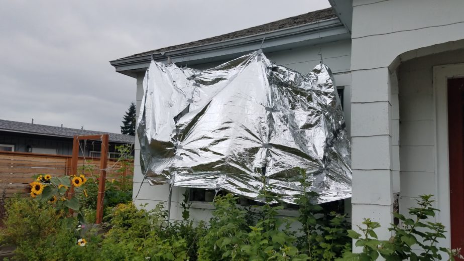
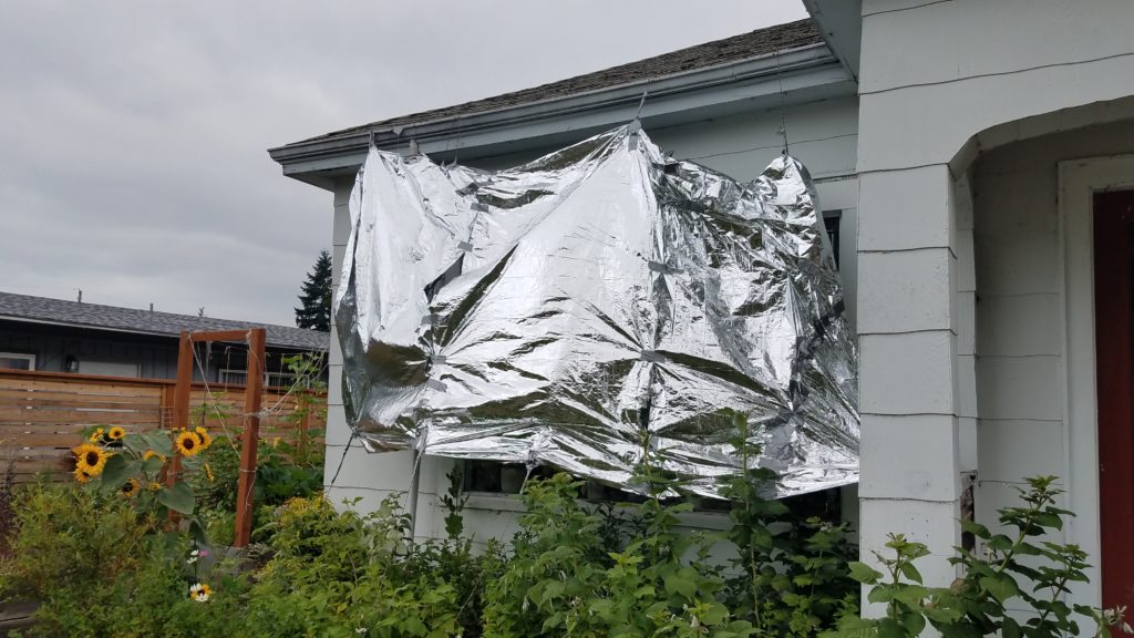
View of the outside of a house with a mylar blanket suspended in front of a large window supported by paracord. There are lots of plants.
Hastily constructed mylar “heat shield”

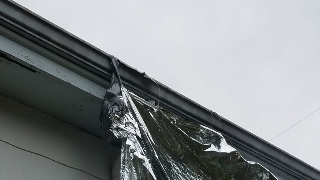
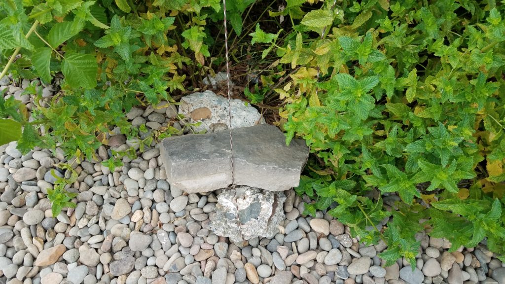
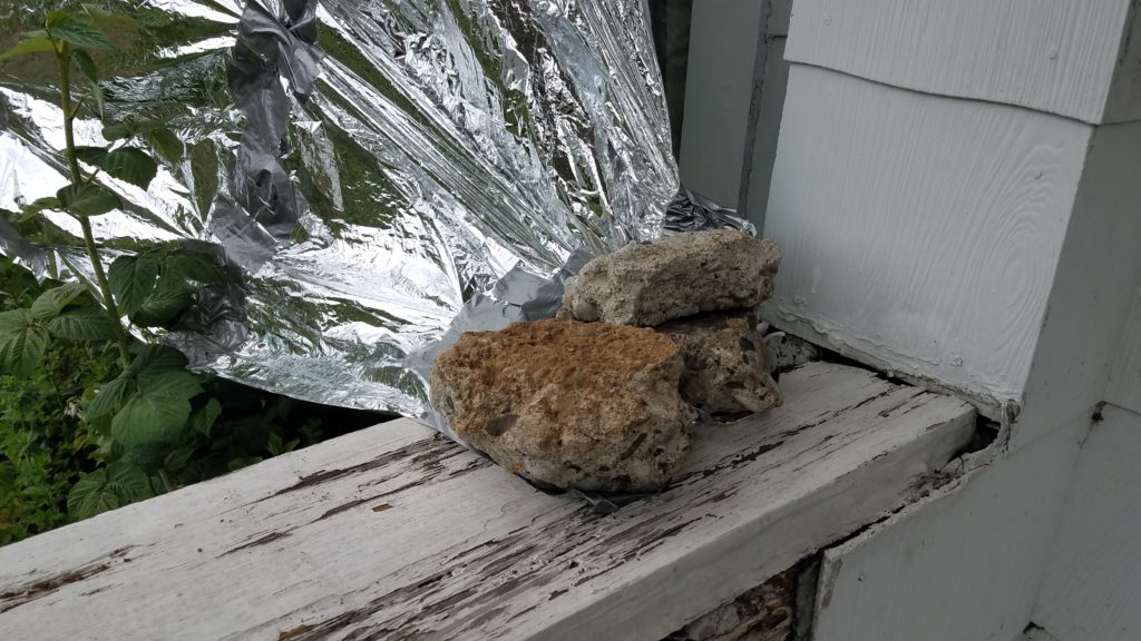
A quick trip to the grocery store yielded the following materials: a roll of duct tape, 50′ of paracord, and 4 mylar blankets (we only needed 3 it turns out). The entire solution cost less than $20, some moderate burns, and sweat. We taped the edges of the mylar blankets on both sides to hold them together and taped across the gap intentionally leaving holes that would be left to ensure the wind loading was lower since this was in part just held up by tape. Our first attempt at the solution was to run paracord from the fence to the gutter, but it required too much paracord and the angle the mylar blanket would be at would be less-than-optimal so I ran the paracord from the ground and weighed the ground ends and center point down with rocks. The end of the paracord attached to the gutter was run between the gutter nails and didn’t require tying or taping. I did, however, end up taping the corner of the mylar blanket to the inside of the rain gutter because there wasn’t a suitable anchor point for paracord near the corner of the house that I wanted to cover. We weighed down one corner with some rocks and were back inside within 35 minutes. Ouch note: ladders get hot in intense sun and gloves are a good idea.

The photos I’m including were taken after day 2. We had to go back out and shore parts of the heat shield up because some of the spots I taped to the paracord slid down. To combat that I just did extra-long wraps of duct tape around the paracord and attached it to the edges of the mylar blankets. I also taped the inside of the shield to the paracord at the bottom to prevent the heat shield from riding up the paracord. The end of the mylar blanket that was weighed down by rocks also tore in the wind/breeze so we coated the corner we stuck the rocks in with duct tape as a protective pad for the mylar. All the photos are this setup are shown below. The air gap between the window and mylar also served as a nice passive cooler. As the breeze and wind blew between the mylar and window it carried some of the heat away. After installing the mylar heat shield the temperature in the house dropped by 10-15 degrees over the next 30 minutes!

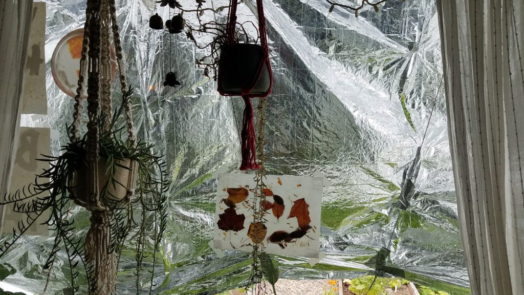
View from the inside of the window showing hanging plants, art work, and the mylar heat shield. Paracord is duct taped to the blakent to keep it off of the window and in position.
View of the back of the heat shield through the window.
One corner of a mylar blanket duct taped to the inside of a rain gutter. The tape is coming off the gutter in spots and the blanket is precariously attached.
Duct taped corner two days after installation. This is the weakest part of the installation.
Paracord tied around two rocks being used as a center point anchor with two "wings" going two directions. Mint and raspberry plants are behind the rocks.
Rocks anchoring the center point of the paracord running from the ground to the gutter. Both ends of the paracord were held down by rocks as well.
One corner of a mylar blanket being covered in duct tape and weighed down by three pieces of broken concrete sitting on a piece of wood in front of some siding.
The duct tape re-enforced corner of the mylar blanket is held down with broken concrete.

Pros:

  • Cheap materials that are readily available
  • Relatively fast to set up on the fly
  • Minimal tooling required to put it up
  • Removable
  • No tape used where it could remove paint
  • Effective at reducing temperature and quickly

Cons:

  • One-time use
  • Will require cutting to get it down
  • Required some maintenance after a day of being up
  • Needs a ladder to set up
  • Required two people to be outside in the heat on the south face of the house for 35 minutes
  • Kinda ugly
  • Dealing with duct tape on top of a ladder in wind wearing gloves is a PITA

Lessons learned

  • I burned myself on the ladder before getting gloves. Don’t get burned.
  • I got sunburned, but when I sweat it dissolves sunscreen so that was expected.
  • I should build something prettier ahead of time that’s easy to take up and down but also cheap to build.
  • Putting a ladder in the middle of a garden bed without absolutely destroying the (very thorny) plants is hard but doable.
  • The mylar blankets in this configuration worked very well!

Modified Ed Fong roll-up dual band J-pole antenna kit

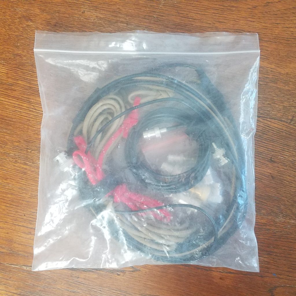
Plastic bag containing a roll-up J-pole antenna and various adapters
Ed Fong roll-up J-pole kit

Howdy y’all! This is my second post for today. I wanted to explain my modified Ed Fong roll-up J-pole antenna and kit. This is the stock Ed Fong DBJ-2 (ham) dual band roll up antenna kit with a twist and an extended adapter pack. The antenna itself is pretty great, but I noticed while using it that there were a couple issues regarding setup. I had trouble hanging it in bushes and trees without carrying some extra materials like paracord. In addition to that sometimes the antenna would snag and you’d need to pull on the attached feed line to get it down which could damage the antenna by weakening connections between the feed line and ladder line or separating them entirely! The antenna comes with a wire tie attached to the end which could be used to hang it from a small object, but it didn’t work well because unless you were hanging it from a small metal object like a nail. Using a J-pole with metal objects near them and above the bottom of the antenna can detune them, and likely increasing the the SWR of your setup. Here’s how I solved both of those problems and set the kit up for a number of radios I and other friends have just in case we needed to hook something different up to it. It has come in handy already.

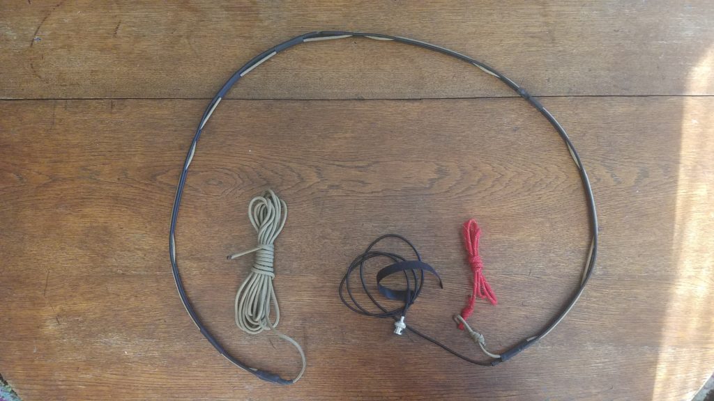
Unrolled j-pole antenna on a wooden table
Unrolled J-pole antenna

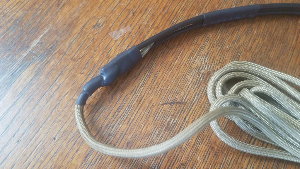
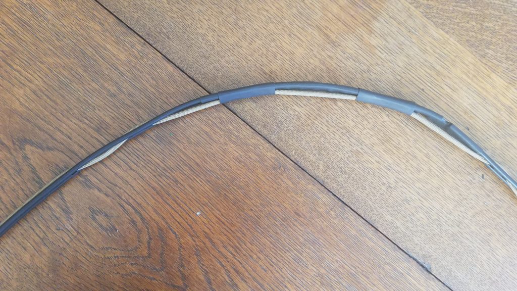
Solving the ease-of-hanging and snagging issues turned out to be the same solution – creative use of inexpensive paracord and heat shrink tubing. The ladder line that serves as the antenna’s radiator has convenient slots that one can weave paracord through. If you tie the paracord to the top of the antenna and weave the paracord through the slots in the antenna you can take a long end and throw it over a branch or tie it to some overhead structure, and also use it as a more rugged line to pull a stuck antenna down with. My initial setup didn’t have enough paracord on the bottom to pull the antenna down when it was up higher and stuck so I added the bright red line to give it more length to retrieve it from a higher location. The bright red length of paracord with a reflective 3M strip woven in also makes it more visible in low light or when you’re looking for the end with a flash light. We can now hang and retrieve our antenna easily and prevent damage to it if there’s a snag you need to apply more pulling force. Here are some more detailed pictures of how the paracord is tied on, woven, and secured by heat shrink tubing.

paracord tied to the antenna with the knot covered by heat shring tubing.
Paracord tied to the top of the antenna and the knot is covered by heat shrink tubing
View of the paracord woven through the antenna and secured by intermittently placed pieces of heat shrink tubing.
Paracord woven through the antenna and intermittently secured by heat shrink tubing
The bottom of the antenna secured with heat shrink tubing and the two sections of the recovery end are tied together

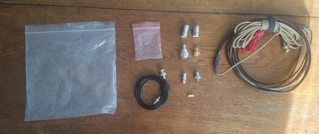
At this point we should probably talk abut the kit in its entirety. The modified antenna is obviously a critical component, but being able to connect the antenna to various radios is also very important. For that we’ll start with an exploded view of the kit.

Plastic bags, cables, adapters, and the cable arranged on a wooden table.
All components of the kit arranged on the table

This kit isn’t anything really fancy. It comes with the stock antenna and male-to-female extended BNC cable. The antenna itself has a BNC end, but not every radio has a BNC connector. I’ve used this antenna with a number of radios including dual-band Kenwood mobile radios, a Baofeng UV-5R, a Yaesu FT3DR, and a Yaesu FT-857D. The two of those radios have a PL-239/SO-239 connector, one has a male SMA, and one has a female SMA connection. This adapter kit allows an operator to connect any radio with a BNC, SMA male, SMA female, or a PL-239/SO-239 connector to the antenna… additionally you can connect one or more pieces of coax with PL-239/SO-239 cables as well. This can be handy if the antenna is up high or if the radio is far from the antenna. Here’s a list of the parts in the graphic top to bottom, left to right:

  • Medium sized heavy plastic zip-loc bag to hold the kit
  • Small heavy plastic zip-loc bag to hold small adapter parts
  • 6′ BNC male to female extension cable (originally came with the antenna)
  • 2x PL-239/SO-239 barrel connectors for both “changing the gender” (I’m not a fan of this terminology, but it’s what’s used broadly) of the BNC to PL-239/SO-239 adapter and for connecting two pieces of feed line together.
  • BNC to PL-239/SO-239 adapter
  • BNC to SMA male adapter with a wide-flanged connector (for my Yaesu HT)
  • BNC to SMA male adapter with a narrow spinning connector
  • BNC to SMA female adapter with a wide-flanged connector
  • BNC female barrel connector for use with the narrow spinning connector to adapt it to a male port
  • Rolled up J-pole antenna

With this set of adapters and cables we can connect this antenna to a wide variety of radios which might be handy in an emergency, or if you happen to forget another antenna. It’s also worth mentioning that this method could also be applied to other roll-up J-pole antennas, not just for ham bands.

Lab599 TX-500 QRP radio kit and friends

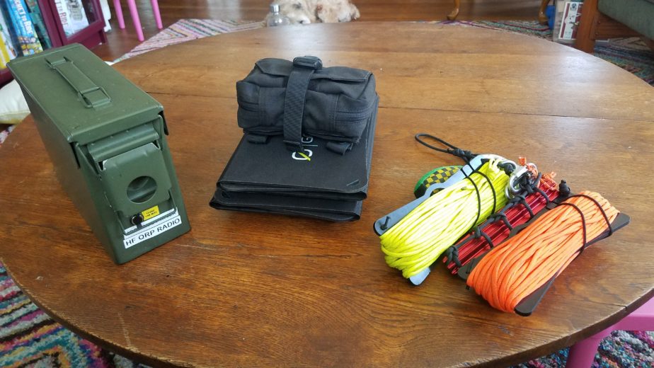
Ammo can, two solar panels with a cloth pouch stacked on top, and a carabiner holding assorted items together on a wood table.
HF QRP radio kit, solar charging kit, antenna hanging kit

Howdy all! This is a new post about my portable QRP radio kit and it supporting kits based around my Lab599 TX-500. Its a fairly self-contained kit but doesn’t have a couple key elements included in the actual box. It doesn’t have any equipment to hang the included trail friendly end-fed half wave dipole or battery charging equipment. I’ll include those elements in this post as well, but they don’t live in the HF radio kit itself. This will be a long post so strap in!

The QRP radio kit

Let’s start with how the HF radio kit is built out. It’s based around a small ammo can I got at a discount store. I wanted to have a fairly self-contained kit that was water resistant and durable and I also wanted the ability to charge and use the battery with the ammo can lid closed to protect against water and dust and ingress. This is by no means waterproof but I wanted to make sure it was at least splash and rain resistant since I do a lot of operating in the Pacific Northwest region of the US which is notorious for its rainy weather.

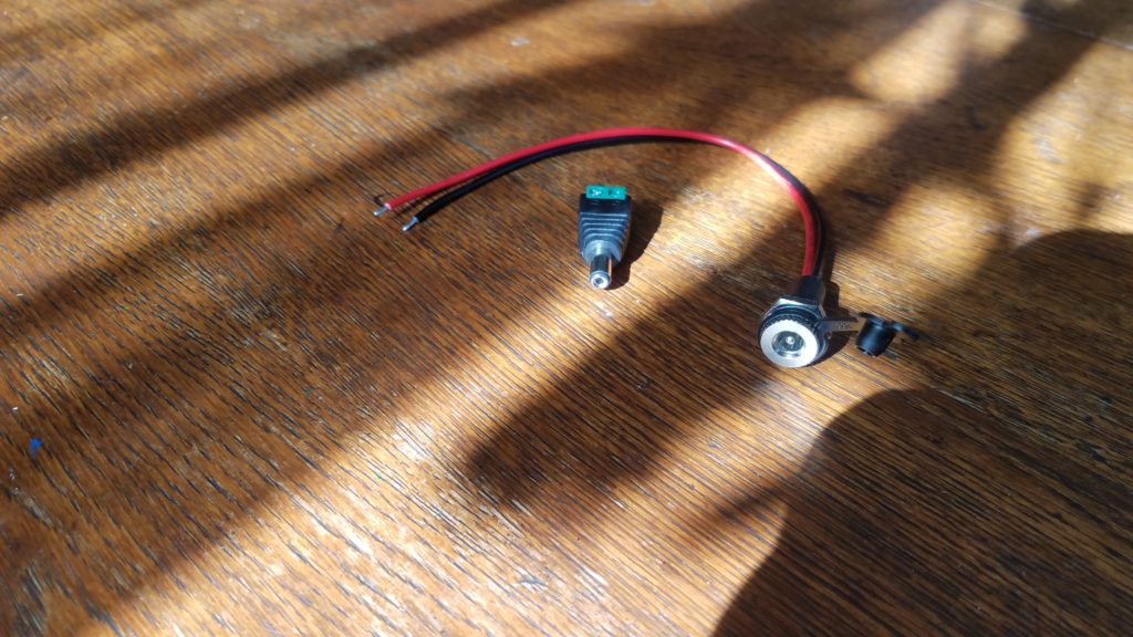
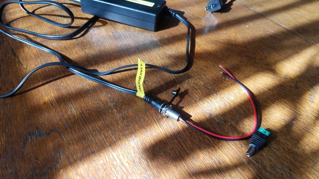
DC barrel jack with wire hanging off and a DC barrel connector with screw terminals on a wood table.
DC barrel connectors
DC barrel jack connected to a AC to DC charger on a wood table.
Testing charger and connector fit

The kit’s battery is a 4.5Ah Bioenno LiFePO4 pack. In order to make sure I can leave that battery in the kit I had to devise a way to connect it to an external charger through the can. After calling the folks at Bioenno I was able to determine the barrel connectors included on their batteries are 5.2 x 2.1mm connectors. The panel mount water resistant connectors I used have 18 gauge wire that supports a max of 10A at 12V DC. I was also able to track down a pack of screw-on terminal barrel connectors as well to connect the battery inside the ammo can. This setup also allows the battery can stay inside the case while the radio is being operated which is good for water and dust resistance. I recommend testing your connections before you drill for both polarity and appropriate voltage levels. In my case they worked fine so I proceeded…

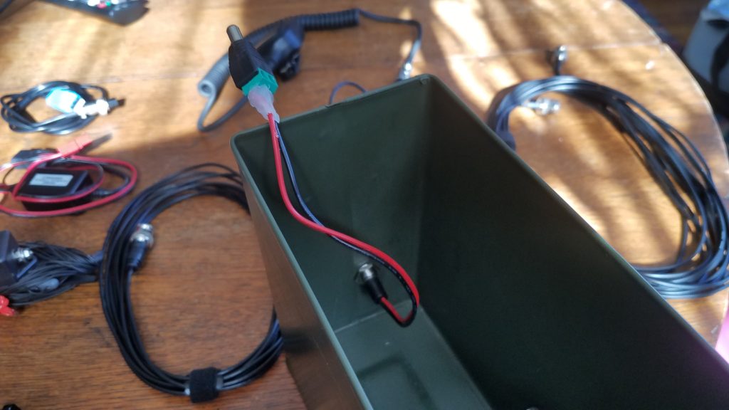
Inside view of an ammo can with barrel connector jack mounted on the front and the DC barrel connector connected to the wire coming from the jack. The barrel connector end's wires are hot glued to the barrel connector. The ammo can is sitting on a wood table and some wires and connectors are sitting on the table in the background.
DC panel mount connector installed in case and insulated screw terminal connector installed

The first consideration in installing the connector is making sure the connector doesn’t interfere with the mechanism on the case that opens/closes it. After that you have to worry about the connector and wire on the inside of the case interfering with items in the case when it’s packed. I decided to place the connector in such a way that the radio laying on its side against the wall of the case would rest against the installed connector. Using a simple metal drill bit I was able to make a hole big enough for the panel mount connector just below the latch mechanism. I then removed any metal burs from the drilled hole and any turnings from the inside of the can to prevent rust, scratching, and short circuits. After installing the panel mount jack and the rubber water/dust cap I just screwed the positive and negative wires into the barrel connector that will hook up to the battery. To ensure no small metal parts caused a short I used hot glue to insulate and strengthen the connection points on the screw terminal barrel connector.

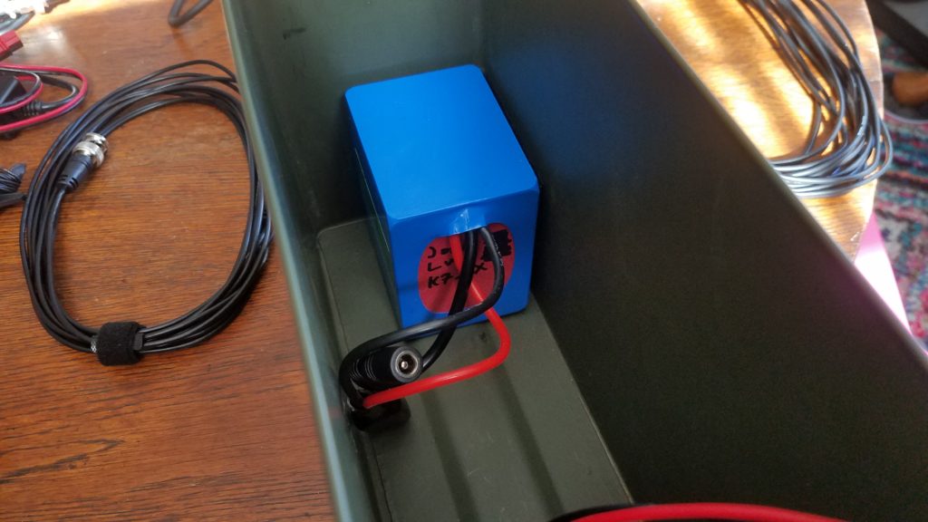
Interior view of an ammo can with a Bioenno battery mounted inside on a wooden table. There are also some wires and connectors sitting on the table in the background.
4.5Ah battery installed in the corner of the ammo can
Interior view of an ammo can with a battery affixed inside and connected to DC barrel connector. A powerpole connector is visible in someone's hand. A wooden table with various cables and connectors is visible in the background.
Battery connected to external DC barrel connector

The next step is adding the battery to the ammo can. I wanted the battery to be semi-permanently mounted in the box so I opted to use 2 x 4″ Velcro strips to secure the battery to two surfaces in the box. the link for those strips is to Amazon but similar strips are available at many stores and websites. The optimum position for the battery seemed to be in a corner where I could install Velcro strips on two of the faces of the corner making it removable without drilling more hols in the can or dealing with metal and glue. Fit testing your equipment is also important when deciding where the battery will be installed. I did that by attaching the loop side of the 2 x 4″ Velcro strips I cut to size to the battery but not removing the plastic that would go on the hook side of the Velcro intended for the inside of the can. Once I was satisfied with the location of the battery and my ability to pack the kit I removed the plastic backing from the hook side of the Velcro and stuck the battery in against the back and corner of the can. I was then able to connect the pass through electrical connection and make sure everything worked properly including polarization of the battery connection. Failing to test the polarity could result in damage to equipment or even potential issues that would compromise the battery. It should also be noted that the radio’s rubber feet make the fit against the battery very tight.

Ammo can and its lid as well as several cables and devices are laid out on a wooden table.
Kit contents + Bioenno 2A AC-DC charger

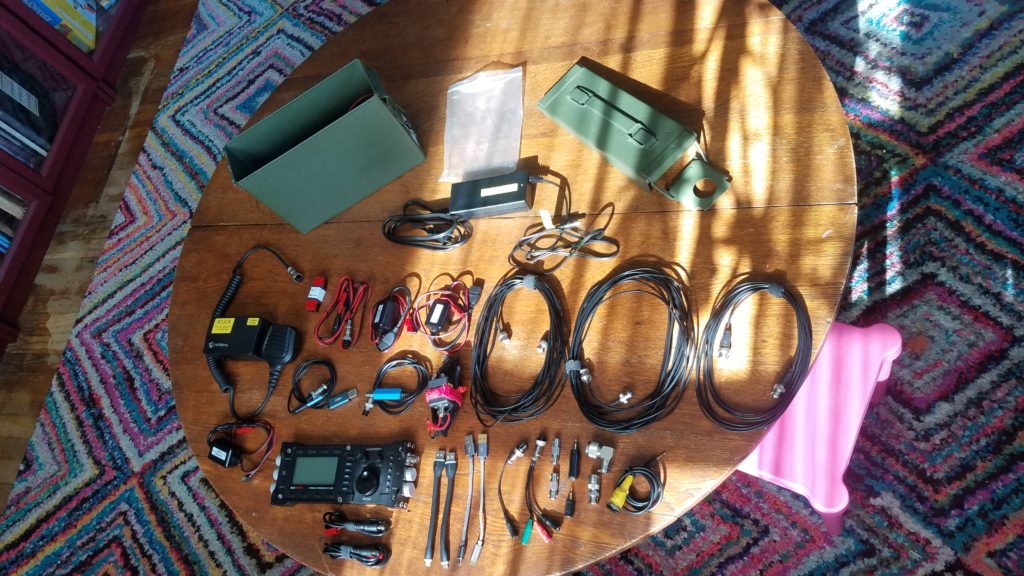
Here’s the contents of the kit. Left to right, top to bottom.

  • Ammo can body with battery and pass through DC cable installed.
  • Plastic bag to hold small adapters and connectors.
  • Ammo can lid
  • Bioenno 2A AC to DC charger for LiFePO4 batteries
  • Lab599 TX-500 speaker mic and Raspberry Pi 4 dedicated to the kit
  • West Mountain Radio PWRnode (4-way Anderson power pole connector in a right-hand-red configuration)
  • Lab599 TX-500 power connector w/Anderson powerpole connector installed in right hand red configuration
  • 2x Powerwerx USBbuddies (12v to 5v USB power converter)
  • 2x 25′ RG-174U cables w/BNC ends (multiple segments of shorter cable allow me to make the shortest connection possible for a given deployment)
  • 15′ RG-174U cable w/BNC ends
  • DIY REM/DATA GX12-7 connector for the TX-500 with a 1/8″ TRRS end connected to a Millso TRRS USB sound card
  • TX-500 USB CAT cable (stock cable that comes w/radio)
  • Par EndFedz trail-friendly EFT-10/20/40m antenna on winder w/BNC connector. This has some red paracord loops attached at each end of the antenna for easier connection to support lines and for visibility.
  • Powerwerx USBbuddy w/spliced-on USB-C connector for the dedicated Raspberry Pi 4. The splice minimizes cable length for less voltage drop and excess cable.
  • TX-500 radio w/3D printed GX-12 series connector dust caps caps installed
  • 2x DIY 5.2 x 2.1mm barrel connector to Anderson Powerpole adapter cables
  • 2x 6″ USB A to MicroUSB cables to connect devices for charging
  • 2x 6″ USB A to USB C cables to connect devices for charging
  • TX-500 morse code (CW) key connection cable (GX12-2 to 1/8″ TS)
  • W2ENY headset adapter wired for a dynamic mic. (The included adapter with the TX-500 was defective from the start in such a way that I’d have to significantly shorten the cable, and I also wanted to use a different PTT button and my existing Heil headset with a dynamic mic element)
  • 2x BNC barrel connectors to connect feed line segments together
  • 1/4″ to 1/8″ TS adapter for PTT switches
  • 1/8″ to 1/8″ TRS to TS adapter for ear buds connected to the speaker mic
  • 90 degree male to female PL-239/SO-239 connector (convenience)
  • BNC to PL-230/SO-239 male adapter (for connecting to most of my other antennas)
  • DIY 1/8″ TS PTT button made from spare parts I had lying around

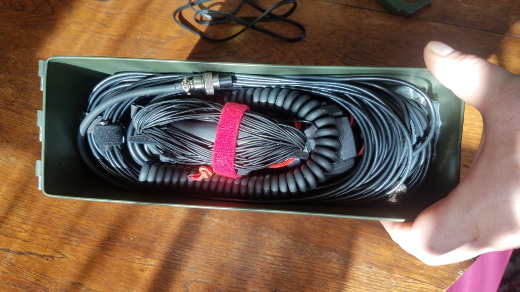
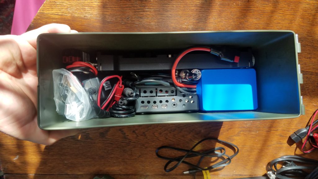
Putting the kit together layer-by-layer is pretty easy. The below photos illustrate how the kit is packed in 3 layers – bottom to top.

Equipment packed into an ammo can.
The first layer at the bottom of the kit – battery, radio, Raspberry Pi, RPi USB C power converter, adpater/connector bag, radio power cable, Powerpole to barrel connector adapters, TX-500 data and CAT cable.
Equipment packed into an ammo can.
The middle layer of the packed kit – 2x USB buddies, all coiled feed line
Equipment packed into an ammo can.
The top layer of the packed kit – Speaker mic and its cable coiled around the trail-friendly antenna

Solar power kit

Now that we’ve covered the kit contents let’s talk field charging with solar power! The solar charging system I typically bring with this radio uses one or two 20W Goal Zero Nomad 20 folding solar panels. Those attach to a Buddipole PowerMini charge controller and power meter. Much of this solar charging kit is composed of cables, but it’s designed to be used with a number of my radios, batteries, portable lights, and USB device chargers.

Two small folded solar panels, one facing up, and the other facing down and a cloth pouch sitting on a wooden table.
Two solar panels and the charger kit

Depending on the deployment I may bring one or both solar panels with the charger kit, or sometimes I’ll just bring the charger kit for power metering to understand how much I’ve drawn my batteries down and at what rate I’m using power. You can check the Buddipole PowerMini’s product page to learn more about it and ways it can be used. In some cases with good sunlight a single 20W panel can provide around 1A (typical max power I’ve gotten from the panels), but in overcast conditions I might use both panels to get 1A peak power. It also might be a good idea to bring both panels to charge at about 2A. It’s especially nice if I expect to charge a phone/tablet and run a radio with a Raspberry Pi if I’m using data modes.

In the above photo you can see the two Goal Zero Nomand 20 solar panels. One of them is staged to show the top view of the panel and the other the bottom view. Each panel has a kick stand to hold itself up at various angles on the ground, cable with an 8mm plug, a USB charging port, and holes in the corners of the panel to suspend them. The Nomad 20s fold open to reveal three solar cells.

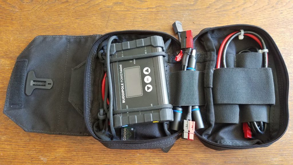
An opened cloth pouch open revealing devices and cables secured to the inside with paracord and elastic bands.
Charger kit opened
An empty cloth pouch, a velcro-backed sleeve, various cables and devices laid out on a wooden table.
Disassembled charger kit

The solar charger kit consists of a Condor MOLLE compatible pouch that has a detachable main pocket which allows you to install and remove the pocket without disconnecting the MOLLE part from the webbing, and also has a loop for easily suspending hanging the kit from something. The kit contains the following items:

  • Condor MOLLE compatible pouch w/ paracord loops to hold and suspend the Buddipole PowerMini
  • Condor MOLLE compatible pouch attachment platform. This comes as a single unit with the pouch listed above.
  • West Mountain Radio PWRNode (4-way Anderson Powerpole connector)
  • DIY MC-4 to Anderson Powerpole connector (for a 100W solar panel not pictured here)
  • BuddiPole PowerMini
  • DIY 2.5″ Anderson Powerpole jumper cable w/10 GA wire (rated for 30A @ 12V DC)
  • DIY 6″ Anderson Powerpole jumper cable w/10 GA wire (rated for 30A @ 12V DC)
  • DIY 4″ Anderson Powerpole to Goal Zero male 8mm connector pigtail.
  • DIY 4″ dual Goal Zero female 8mm plug to Anderson Powerpole pigtail. This allows the two Goal Zero solar panels to be used simultaneously.
  • DIY 3′ Female Goal Zero 8mm to Anderson Powerpole cable.

You’ll probably notice there are a lot of seemingly redundant connectors and pigtails in this kit. There’s a reason I carry so many adapters around, and that is to make sure I can run as little cable as possible to achieve connections between system components. Being able to use shorter cables help limit voltage drop, but having the option to use a longer cable to connect the solar panels might mean I can stay in the shade and keep my solar panels in the sun. The short Anderson Powerpole jumpers included in the kit can help me connect to the battery or connect a PWRNode to the PowerMini. The Anderson Powerpole connectors on the side of the PowerMini don’t allow you to connect the PWRNode directly to it, and even if they did you’d lose two of the four connections on the PowerMini side of the PWRNode. In most cases this kit powers the entire radio doing phone and data, a phone and tablet, etc. Most of the time the equipment barely uses the battery while operating during the day and I have a full battery to use at night for the radio and lights.

Antenna hanging kit

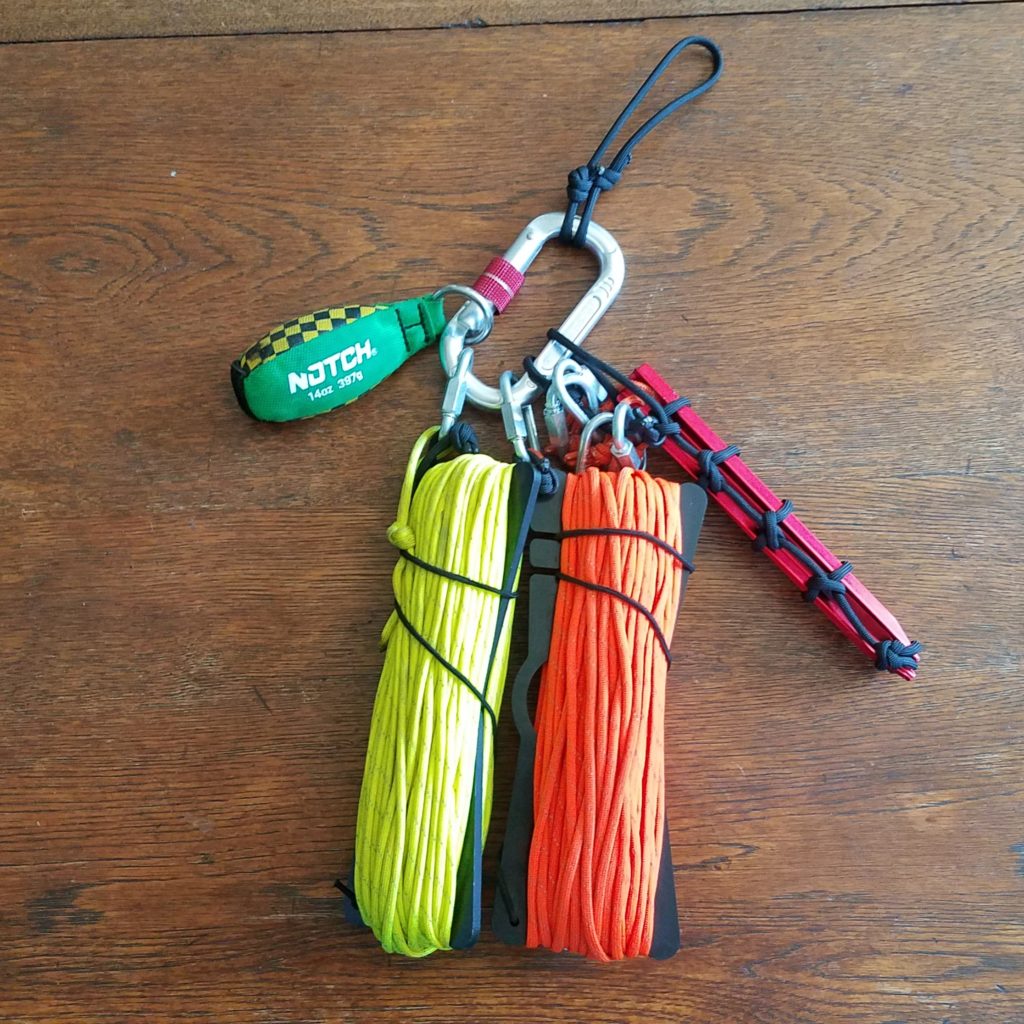
Two hanks of paracord, a throwing weight, and tent stakes mounted to a carabiner sitting on a wooden table.
Antenna hanging kit

Last but not least we have the antenna hanging kit. It’s great to have a radio and a way to power it, but if you can’t get your antenna where it needs to be it’s all for nothing. This part of the kit rounds off the portable radio station. It’s designed to work with a number of wire antennas I have – a Par EndFedz 6m antenna, the Chameleon EMCOMM III Portable, and the Par EndFedz EFT-10/20/40 trail friendly antenna that lives in the HF radio kit. In the case of the trail friendly antenna we require two points of suspension for horizontal dipole operation – the end of the wire antenna and the transformer component. Being in Oregon and setting up my radio station in the region quite a bit I frequently rely on trees as antenna supports, and thus also pack an arborist’s weight as part of my equipment to assist in hanging the line. It adds a lot of weight but is definitely worth it. Using rocks and other tree branches works but definitely comes with snagging risks and the possibility your line will come off of the wight you’re using to get the line up… especially when it comes to rocks. I carry 4 aluminum tent stakes with paracord loops and quick links for attaching line. Those are bound during transport by a piece of paracord I tied together to make the clanking of the tent stakes go away and to keep them from flopping everywhere. There are four aluminum tent stakes in the kit because I might want to anchor my Chameleon EMCOMM III in 3 or 4 spots depending on antenna configuration. I have two 75′ high visibility paracord hanks wound around Chameleon wire winders that can support two ends of antennas that are in a horizontal dipole configuration. Each hank of paracord has a quick link attached for connecting to the ends of an antenna or suspension point, and the arborist’s weight for deployment. I can leave one of the paracord hanks behind if I want to set an antenna up in a configuration that only requires one suspension point like an inverted V. I added a small loop of paracord to the Chameleon wire winders in one of the corner holes to take the weight of the assembly off of the elastic band that wraps the paracord when the hank is being stored or transported. The locking carabiner is used to hold everything together, clip the kit onto something like a backpack, or hang it from a pocket during setup. The specific carabiner I’m using is probably overkill but I had it laying around so I used it. There’s also another loop of paracord attached to the carabiner which acts as a more comfortable carrying handle and for storage by hanging from a door knob.

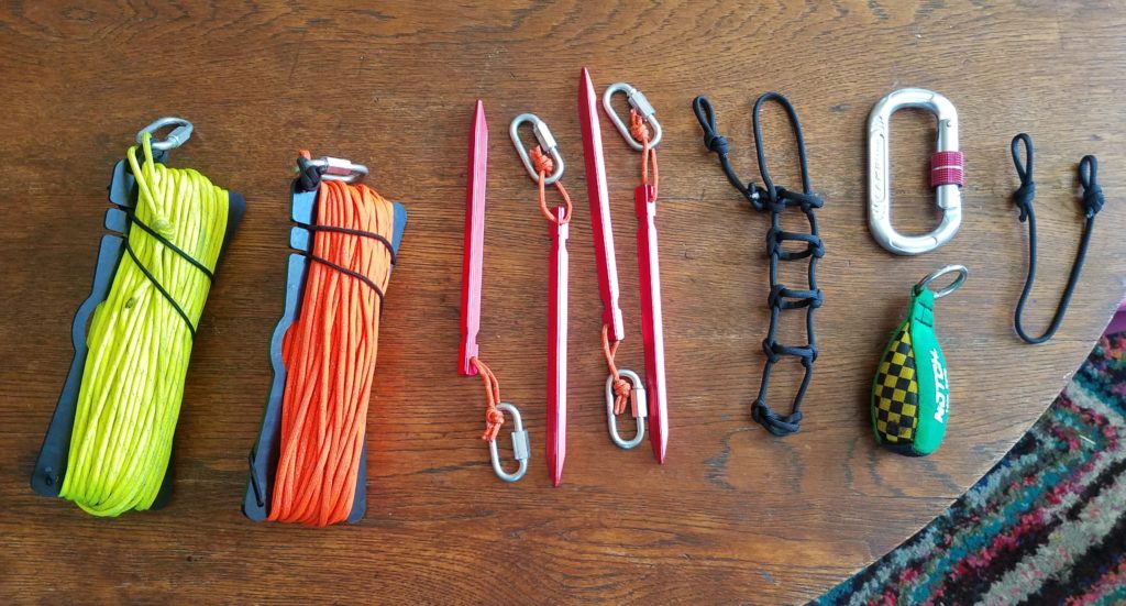
Antenna hanging equipment laid out on a wooden table.
The antenna hanger kit broken down to (most) of its individual components

Kit parts list below:

  • Notch 14oz arborist’s weight
  • Camp locking carabiner
  • Black paracord cut small into smaller pieces for use as a handle, 2x wire winder strain relief loops, and a keeper for the tent stakes (don’t ask me how I figured out how to tie that. I can’t really tell you how I did it except that I did a lot of experimentation.
  • 2x Chameleon wire winders
  • 6x threaded quick links (4 on stakes, 2 on the 75′ paracord)
  • 2x high visibility 75 ft paracord hanks w/ 3M high visibility strip included for working on the antenna suspension at night
Detailed view of tent stakes secured in a paracord sleeve.
Tent stake holder assembled

Note the paracord attachment point run through the quick links that make sure they don’t come out of the holder or make a bunch of noise. Both loops of black paracord go through the carabiner, but if you remove the attachment point with the quick links from the carabiner it’s easy to just pull the quick links off.

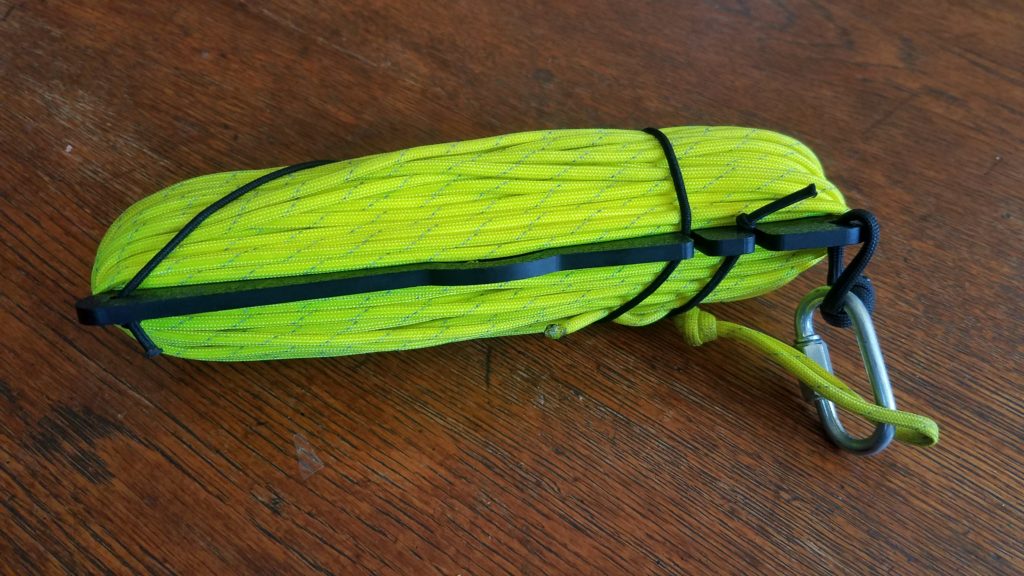
Chameleon wire winder with bright yellow paracord wrapped around it and secured to the wire winder by an elastic band. The paracord and wire winder are connected together with a quick link.
75′ high vis paracord wrapped around Chameleon wire winder and set up for transport

This is a more detailed view of one of the two paracord hanks. Both are set up the same way. The paracord is wrapped around the Chameleon wire winder and is held on the winder using the built-in elastic band which is wrapped around the paracord and secured with the pictured notches. The quick link is attached to the throw/attachment end of the paracord, and the quick link is also attached to the small black loop of paracord to take strain off of the elastic band during transport. This design uses the quick link, black paracord loop, and plastic wire winder plate to take the weight of the assembly when attached to the carabiner.

Connecting it all

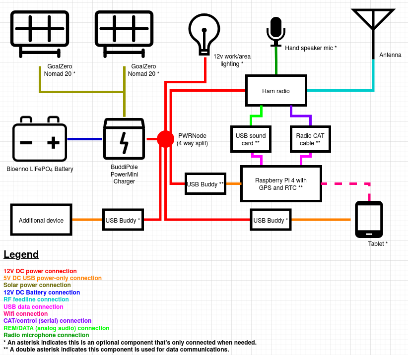
While this isn’t necessarily directly related to the composition of the kits I described above I decided to diagram out how the station is wired up for my typical use and add this section after I wrote the original post. You’ll note that some components are only used in data operations, and some are only hooked up when needed. For example, I won’t need the light unless it’s dark, I won’t want to use the Raspberry Pi unless I’m doing data comms or using the documentation server. In addition I won’t have any of the USB buddies that I don’t need hooked up at any time because they draw power, and unless I want that power to go to something I just won’t use it. If I’m deploying at night and don’t expect to stick around until morning I won’t deploy the solar panels and add the hassle of managing those additional cables and connections. In any case, this is basically how it’s all wired up for my typical deployments. Sometimes I’ll use different components such as a 100W solar panel instead of the 20s, or add a travel router and a USB buddy to the data deployment depending on my situation and available power/battery.

Diagram showing interconnection of components with various colored lines.

Wrapping it up

So, this is the kits! I don’t always use the trail-friendly antenna with this radio, but it’s what I include in the kit by default. I also use a Samsung Galaxy tablet and sometimes a customized travel wireless router in conjunction with this kit when I do data mode work to interact with the Raspberry Pi 4 in this kit and / or one of the other ones I have set up, but that’s a whole other post.

Raspberry Pi document server

When operating in a grid down or off-grid scenario it is often important to have access to information, maps, manuals, forms, frequency plans, emergency plans, etc. This guide seeks to explain how to install and populate the document server with info.

First, using either SSH or the terminal application on your Pi install git.

sudo apt-get install git

Next, read the documentation for document-server. This will tell you how to install it and its dependencies.

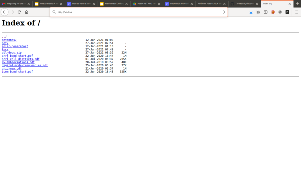
Once installed you can copy any required documents to the pi user’s Documents folder. I strongly recommend you use PDF and text formats, and images rather than word documents or other formats that require more specialized applications to open. When you load the page using the Raspberry Pi’s hostname or IP address via http://<IP or hostname>. You’ll be presented with your documents! They can now be opened from any device that has a web browser and can open the files you stored.

As extra credit I also create a zip file with all my documents so you can download all the documents at once if need be. This can be useful when you want a copy of all documents so you don’t need the Pi to be powered on in order to read information.

Optional Avahi configuration

In order to advertise services to devices that support MDNS you can add the following configuration to /etc/avahi/services/documents.service and then restart Avahi: sudo systemctl restart avahi-daemon

<?xml version="1.0" standalone='no'?><!--*-nxml-*-->
<!DOCTYPE service-group SYSTEM "avahi-service.dtd">
<service-group>
  <name replace-wildcards="yes">%h Documents</name>
  <service>
    <type>_http._tcp</type>
    <port>80</port>
  </service>
</service-group>

Portable UHF/VHF Winlink host

Howdy! I had recently posted about some Raspberry Pi based systems that can be used in the shack or in the field and those posts received a lot of questions about how they were set up. This post is the first in a series that seeks to explain the design, operation, and setup of these hosts. Some of the work I did here was inspired by Julian, OH8STN’s general off grid/grid down operating philosophy and K1CHN’s blog posts.

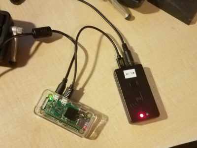
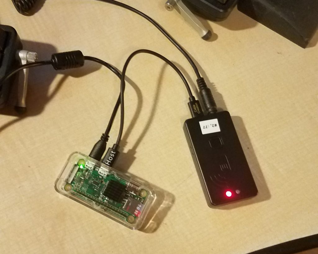
A Raspberry Pi W Zero in a clear acrylic case connected to a Mobilinkd TNC3 with a MicroUSB OTG cable, host end connected to the Pi's USB OTG port.
Raspberry Pi Zero W connected to Moblinkd TNC3 using a MicroUSB OTG cable.

So, what are we talking about here?

  • A Raspberry Pi Zero W / Raspbian based Pat Winlink host.
  • Designed to work with packet on UHF/VHF radios.
  • Compatible with a wide range of radios.
  • Runs on USB or 12v and has typical 45A Anderson PowerPole connectors in a “right hand red” configuration when running on 12v. This matches my off grid power setup and the ARES + RACES standards.
  • Uses a Mobilinkd TNC3 to work with a variety of UHF/VHF radios and to offload signal processing to a TNC. That means we don’t need as much processing power on the compute node. Multiple adapter cables are sold on the Mobilinkd store and you can make your own.
  • Automatically sets up and tears down the AX.25 port and connection based on the status of the TNC’s USB connection.
  • Nice, tidy web interface that can be used by any device with wifi capabilities and a fairly modern browser to send and receive e-mail.

Parts list:

  • Raspberry Pi Zero W and power supply
  • MicroSD card
  • Optional Pi Zero W case
  • Mobilinkd TNC3
  • Appropriate cable, purchased or constructed to connect from the TRRS jack on the TNC3 to your UHF/VHF radio
  • MicroUSB OTG cable for the Pi to TNC3 connection.
  • Optional USBBuddy (12v to 5v USB down converter)
  • Optionally short USB A to MicroUSB cable to cut down on voltage drop.
  • UHF/VHF radio of choice. This setup has been tested with a Baofeng UV-5R, Yaesu FT-857D, Yaesu FT-3DR, Kenwood TM-D710G, and a Kenwood TM-V71 but should work with many others. The Mobilinkd TNC3 was designed to work with a broad range of radios.

Theory of operation:

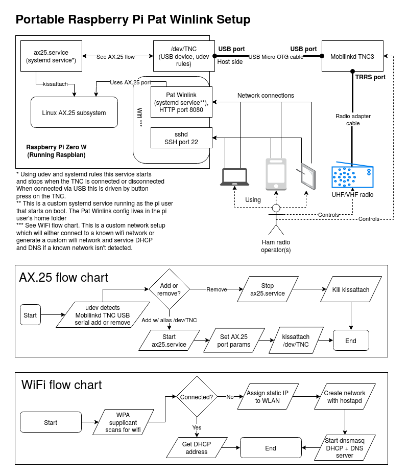
Block diagram showing control flows between and connections between the operator, radio, devices, and between the TNC and Raspberry Pi. The diagram also depicts the control flows between the TNC, ax25.service, Linux AX.25 subsystem, and Pat Winlink. Flow charts depict AX.25 service flows and a wifi flow chart describing when the system decides to host its own wifi.
Block diagram showing various system components and their interactions. Flow charts for managing the AX.25 service and self-hosted wifi.

The Pi leverages a number of smaller subsystems to provide e-mail access.

  1. Scripts and applications that provide AX.25 setup and teardown as the TNC is connected or disconnected. These scripts leverage udev and systemd to detect state changes on the TNC. While you can use Bluetooth to maintain these connections it’s easier and more simple to control connections to the TNC using its USB connection status.
  2. A set of scripts, services, and utilities that automatically provide a functional wireless network in the event the Pi is unable to connect to a known network. This includes DNS and DHCP.
  3. Pat Winlink is run as a systemd service so the operator doesn’t have to worry about starting and stopping the service. It can run in the background whether or not the TNC is connected, but it can’t send or recieve e-mail without the TNC connected.
  4. Pat Winlink is accessed via a web interface. You need a phone, tablet, or computer that can connect to the wireless network generated by the Pi, or is on the same network as the Winlink server. This allows an operator to use Winlink.

Setup process

Start by installing Raspbian on your MicroSD card and getting your Raspberry Pi up and running. The steps here should work. Make sure you give your pi a hostname like “winlink” or whatever you’d like. If you configure dnsmasq this becomes important. Once your Pi is up and running with an Internet connection we can pre-install needed utilities and software so we don’t have to do it later. We’ll also make sure dnsmasq and hostapd don’t start automatically (more on this later). These commands can be done from the Raspberry Pi’s terminal application or from an SSH session if you’ve enabled it:

sudo apt-get update -y && sudo apt-get upgrade -y
sudo apt-get install libax25 libax25-dev ax25-apps ax25-tools dnsmasq hostapd git
sudo systemctl disable hostapd
sudo systemctl disable dnsmasq

Once we have all that installed we’ll install and configure Pat Winlink. Download the latest Pat Winlink release from GitHub. You’ll want to make sure you choose the armhf (Raspberry Pi) .deb file. Make sure you note the name of the file as it will be important when running the install command. When you’re ready to upgrade Pat Winlink in the future you can download the newest version of the .deb file from the same page. Assuming you’ve downloaded the file to the Downloads folder you can run the following command to install Pat Winlink, replacing “pat_0.10.0_linux_armhf.deb” with whatever file name you downloaded:

sudo dpkg -i ~/Downloads/pat_0.10.0_linux_armhf.deb
mkdir ~/.wl2k

After we configure our AX.25 settings we can come back to configuring Pat Winlink as we’ll need some values from that setup.

Next we’ll edit /etc/ax25/axports. This file configures our AX.25 ports that get used to build connections to packet Winlink gateways. Mine looks like this. You’ll of course want to replace my callsign with yours. The port we configure below will be called wl2k. This will be needed for the Winlink configuration in a number of spots.

# /etc/ax25/axports
#
# The format of this file is:
#
# name callsign speed paclen window description
#
wl2k K7JLX 9600 255 7 Winlink (9600)

In the next step we’ll create three files – a script that manages AX.25 port connections, a systemd service that manages the AX.25 port, and finally a udev rule that starts and stops that systemd service when the Mobilinkd TNC3 shows up as a USB serial device or is disconnected.

First, let’s install ax25-up, a script in the Winlink project that manages AX.25 connections. Our systemd unit depends on it. The commands in this step come from here, but are slightly modified to put the script in a different location on the Pi.

bin="/usr/sbin/ax25-up"
sudo curl -o $bin https://raw.githubusercontent.com/la5nta/pat/master/share/bin/axup
sudo chmod +x $bin

Next we’ll add the udev rules that work with systemd to start and stop the service. Add the following contents to /etc/udev/rules.d/99-hamradio.rules:

# Mobilinkd TNC3
ACTION=="add", ATTRS{idVendor}=="0483", ATTRS{idProduct}=="5740", ATTRS{manufacturer}=="Mobilinkd LLC", SYMLINK+="ttyTNC", TAG+="systemd", ENV{SYSTEMD_WANTS}="ax25.service"
ACTION=="remove", SUBSYSTEM=="usb", ENV{PRODUCT}=="483/5740/200", TAG+="systemd"

We’ll now create our systemd unit file which should be: /usr/lib/systemd/system/ax25.service Note the ExecStart command where we use our wl2k port, and /dev/ttyTNC as created by our udev rules. That device is created in the event we attach another USB serial device to create a predictable name no matter what the proper udev name of the device is.

[Unit]
Description=AX.25 KISS interface
Before=network.target
Wants=network.target
BindsTo=dev-ttyTNC.device
After=dev-ttyTNC.device
[Service]
Type=oneshot
RemainAfterExit=yes
ExecStart=/usr/sbin/ax25-up /dev/ttyTNC wl2k 9600
ExecStop=killall kissattach
KillMode=none
[Install]
WantedBy=multi-user.target

Configuring and setting Pat Winlink up as a service

First we’re going to put in a configuration for Pat Winlink. We’ll do that by editing ~/.wl2k/config.json. You’ll want to replace the values I have in my configuration with your own. I’m connecting to a station called W7LT-10 most of the time. You’ll also want to remove your password until you’ve set one. Follow these instructions for that process. Replace your callsign and grid square locator with your own. You may also want to add your own connect_alias entries. These can be various Winlink stations you want to “bookmark” for quick connection. I’ve added a number of them for use while I’m out camping. In that list you might have noticed the one beginning with “!W7LT-10”. Since I use that one most commonly I added an ! to the front of the name to keep it at the very top of the list when it’s alphabetized by the Pat Winlink application. The http_addr directive tells Pat Winlink to listen on any address on port 8080. This will be important when constructing the URL to access Pat Winlink with. You may also notice that I’ve configured this to listen on ax.25 and telnet. This allows the Pat Winlink application to listen in peer-to-peer mode for incoming connections. You don’t have to switch between peer-to-peer and CMS mode manually like you would using Winlink Express. You may want to assign a new telnet password if you want to keep the listen entry for telnet.

{
  "mycall": "K7JLX",
  "secure_login_password": "VerySecret",
  "http_addr": "0.0.0.0:8080",
  "listen": ["ax25", "telnet"],
  "locator": "CN85qm",
  "motd": ["K7JLX Pat Winlink stn"],
  "connect_aliases": {
    "!W7LT-10, 144.910MHz, PDX": "ax25:///W7LT-10?freq=144910",
    "K7HWY-11, 145.030MHz, La Pine, OR": "ax25:///K7HWY-11?freq=145030",
    "KB7EOC-10, 144.950, Tillamook, OR": "ax25:///KB7EOC-10?freq=144950",
    "KG7AV-10, 145.030MHz, Bend, OR": "ax25:///KG7AV-10?freq=145030",
    "W7EUG-10, 145.030MHz, Eugene, OR": "ax25:///W7EUG-10?freq=145030",
    "W7GC-11, 144.950, Hebo Lake, OR": "ax25:///W7GC-11?freq=144950",
    "WC7EOC-10, 144.980MHz, Hillboro, OR": "ax25:///WC7EOC-10?freq=144980",
    "WW7CH-10, 145.050MHz, Eatonville, WA": "ax25://WW7CH-10?freq=145050",
    "N7GWK-10, 145.630MHz, Centrailia, WA": "ax25://N7GWK-10?freq=145630",
    "N7DEM-10, 144.920MHz, Longview, WA": "ax25://N7DEM-10?freq=144920",
    "W7BO-10, 144.920MHz, Woodland, WA": "ax25://W7BO-10?freq=144920",
    "KA7CTT-10, 144.920MHz, Vancouver, WA": "ax25://KA7CTT-10?freq=144920",
    "W6TQF-10, 145.055MHz, Underwood, WA": "ax25://W6TQF-10?freq=145055",
    "N7YRC-10, 144.930MHz, Yakima, WA": "ax25://N7YRC-10?freq=144930"
  },
  "ax25": {
    "port": "wl2k"
  },
  "telnet": {
    "listen_addr": ":8774",
    "password": "AlsoVerySecret" 
  }
}

Now that we have a solid initial configuration let’s set Pat Winlink up as a service that starts automatically when the Pi boots. The first step is creating a new systemd unit at /lib/systemd/system/pat.service which will run as the standard pi user that ships with Raspbian. The contents of that systemd service are as follows:

[Unit]
Description=Pat Winlink HTTP server
After=ax25.service
[Service]
Type=simple
ExecStart=/usr/bin/pat http
User=pi
Group=pi
[Install]
WantedBy=default.target

Now we start and enable the service by running some commands in the terminal. The last command should show Pat up and running with a green “active” status. You can press “q” to quit the status display.

sudo systemctl enable pat
sudo systemctl start pat
sudo systemctl status pat

To test all the work we’ve done thus far reboot your Raspberry Pi using the GUI or by issuing the following command in the terminal:

sudo shutdown -r now

Once your Pi is back up and you’re logged back in as the pi user we’ll connect the Mobilinkd TNC3 to the Pi using the MicroUSB OTG cable. The host side connects to the Pi’s USB port, not the power port. After plugging the cable in press the connect button on the Mobilind TNC3. You’ll see a yellow flash on the TNC’s status LED. This momentary button press should trigger the ax.25 systemd service to start. We can check on that by running the following command:

sudo systemctl status ax25

If you see that the service is active and green you’re good to go on the base Winlink functionality. The only thing left to do is connect to it. Use your browser connect access Winlink with a URL derived from this template: http://<your winlink hostname or IP>:8080

If you want an automatic hotspot proceed to the next step.

Automatic hotspot

For this part of the guide just follow the steps that Raspberry Connect lists. You can modify their scripts to create IP addresses and wireless network names/passwords as needed. You can modify the /usr/bin/autohotspotN script and set the IP address there. In the createAdhocNetwork() function modify the ip a add line with the desired IP and subnet mask.

After the scripts scripts have been run and things have been configured you can optionally set up DNS records in dnsmasq. My configuration looks like this but yours will certainly vary. The static IP addresses and DNS records help Android devices or other systems that don’t work well with MDNS find your winlink service. You can use any network you want. The dhcp-host line for winlink.local is commented out because the host we’re running won’t get a DHCP address from itself. The additional entries help other Raspberry Pis or other devices get static IPs and allow them to be found by hosts. In this way we can make sure any devices that connect to your network that offer services show up. Make sure the ‘address’ line matches the hostname of your pi, and that the IP matches the one you set after the RaspberyConnect’s script run in the previous steps.

interface=wlan0
no-resolv
bind-interfaces
dhcp-range=192.168.255.20,192.168.255.250,4h
address=/ft857d.local/192.168.255.1
dhcp-host=dc:a6:32:11:11:11,192.168.255.1
address=/winlink.local/192.168.255.2
#dhcp-host=b8:27:eb:22:22:22,192.168.255.2
address=/tx500.local/192.168.255.3
dhcp-host=dc:a6:32:33:33:33,192.168.255.3

Multicast DNS (MDNS)

To help devices that support MDNS automatically discover the winlink service we can add a configuration file to Avahi. To do that create a file at /etc/avahi/services/winlink.service:

<?xml version="1.0" standalone='no'?>
<!DOCTYPE service-group SYSTEM "avahi-service.dtd">
<service-group>
  <name replace-wildcards="yes">Winlink on %h</name>
  <service>
    <type>_http._tcp</type>
    <port>8080</port>
  </service>
</service-group>

Now restart Avahi using the following commands:

sudo systemctl restart avahi

At this point if your pi can’t reach a known wifi network it should start its own. Make sure you test it before you need it to work in a real-life situation.

As a bonus you can create a document server on the Pi to make sure you have information, forms, manuals, etc. when you need them in the field.

Updates to this blog entry:

4 Sep, 2021 – The Pat Winlink configuration section was updated to reflect changes I’ve made since the original draft of this entry.