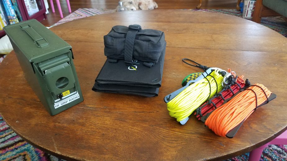

Howdy all! This is a new post about my portable QRP radio kit and it supporting kits based around my Lab599 TX-500. Its a fairly self-contained kit but doesn’t have a couple key elements included in the actual box. It doesn’t have any equipment to hang the included trail friendly end-fed half wave dipole or battery charging equipment. I’ll include those elements in this post as well, but they don’t live in the HF radio kit itself. This will be a long post so strap in!
The QRP radio kit
Let’s start with how the HF radio kit is built out. It’s based around a small ammo can I got at a discount store. I wanted to have a fairly self-contained kit that was water resistant and durable and I also wanted the ability to charge and use the battery with the ammo can lid closed to protect against water and dust and ingress. This is by no means waterproof but I wanted to make sure it was at least splash and rain resistant since I do a lot of operating in the Pacific Northwest region of the US which is notorious for its rainy weather.
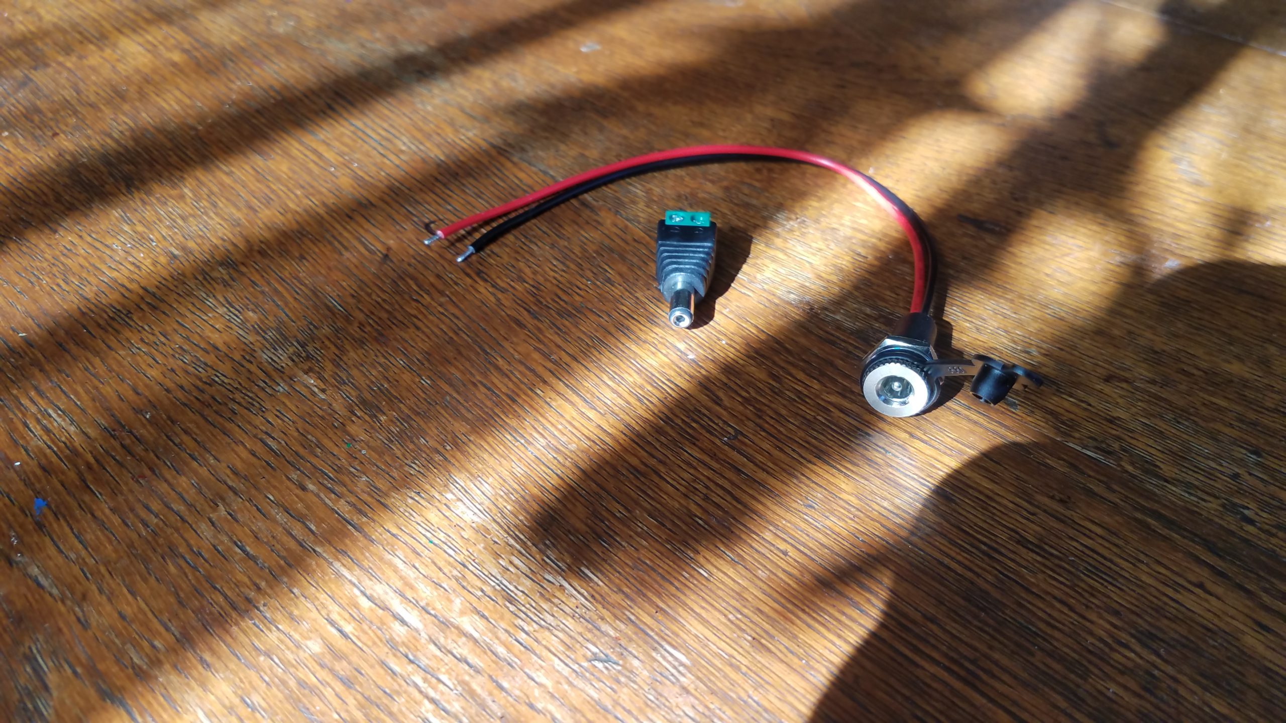

The kit’s battery is a 4.5Ah Bioenno LiFePO4 pack. In order to make sure I can leave that battery in the kit I had to devise a way to connect it to an external charger through the can. After calling the folks at Bioenno I was able to determine the barrel connectors included on their batteries are 5.2 x 2.1mm connectors. The panel mount water resistant connectors I used have 18 gauge wire that supports a max of 10A at 12V DC. I was also able to track down a pack of screw-on terminal barrel connectors as well to connect the battery inside the ammo can. This setup also allows the battery can stay inside the case while the radio is being operated which is good for water and dust resistance. I recommend testing your connections before you drill for both polarity and appropriate voltage levels. In my case they worked fine so I proceeded…
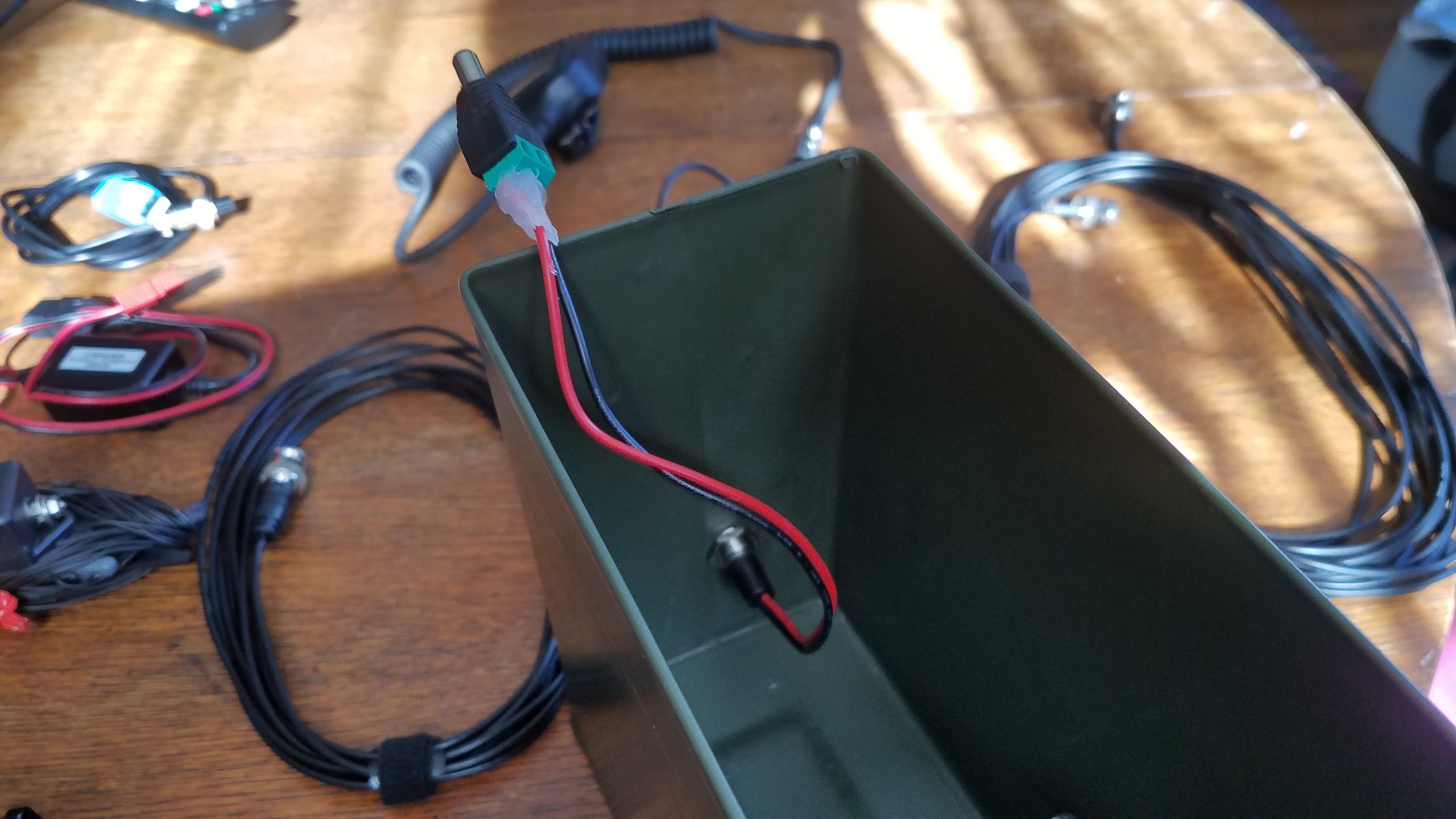
The first consideration in installing the connector is making sure the connector doesn’t interfere with the mechanism on the case that opens/closes it. After that you have to worry about the connector and wire on the inside of the case interfering with items in the case when it’s packed. I decided to place the connector in such a way that the radio laying on its side against the wall of the case would rest against the installed connector. Using a simple metal drill bit I was able to make a hole big enough for the panel mount connector just below the latch mechanism. I then removed any metal burs from the drilled hole and any turnings from the inside of the can to prevent rust, scratching, and short circuits. After installing the panel mount jack and the rubber water/dust cap I just screwed the positive and negative wires into the barrel connector that will hook up to the battery. To ensure no small metal parts caused a short I used hot glue to insulate and strengthen the connection points on the screw terminal barrel connector.


The next step is adding the battery to the ammo can. I wanted the battery to be semi-permanently mounted in the box so I opted to use 2 x 4″ Velcro strips to secure the battery to two surfaces in the box. the link for those strips is to Amazon but similar strips are available at many stores and websites. The optimum position for the battery seemed to be in a corner where I could install Velcro strips on two of the faces of the corner making it removable without drilling more hols in the can or dealing with metal and glue. Fit testing your equipment is also important when deciding where the battery will be installed. I did that by attaching the loop side of the 2 x 4″ Velcro strips I cut to size to the battery but not removing the plastic that would go on the hook side of the Velcro intended for the inside of the can. Once I was satisfied with the location of the battery and my ability to pack the kit I removed the plastic backing from the hook side of the Velcro and stuck the battery in against the back and corner of the can. I was then able to connect the pass through electrical connection and make sure everything worked properly including polarization of the battery connection. Failing to test the polarity could result in damage to equipment or even potential issues that would compromise the battery. It should also be noted that the radio’s rubber feet make the fit against the battery very tight.

Here’s the contents of the kit. Left to right, top to bottom.
- Ammo can body with battery and pass through DC cable installed.
- Plastic bag to hold small adapters and connectors.
- Ammo can lid
- Bioenno 2A AC to DC charger for LiFePO4 batteries
- Lab599 TX-500 speaker mic and Raspberry Pi 4 dedicated to the kit
- West Mountain Radio PWRnode (4-way Anderson power pole connector in a right-hand-red configuration)
- Lab599 TX-500 power connector w/Anderson powerpole connector installed in right hand red configuration
- 2x Powerwerx USBbuddies (12v to 5v USB power converter)
- 2x 25′ RG-174U cables w/BNC ends (multiple segments of shorter cable allow me to make the shortest connection possible for a given deployment)
- 15′ RG-174U cable w/BNC ends
- DIY REM/DATA GX12-7 connector for the TX-500 with a 1/8″ TRRS end connected to a Millso TRRS USB sound card
- TX-500 USB CAT cable (stock cable that comes w/radio)
- Par EndFedz trail-friendly EFT-10/20/40m antenna on winder w/BNC connector. This has some red paracord loops attached at each end of the antenna for easier connection to support lines and for visibility.
- Powerwerx USBbuddy w/spliced-on USB-C connector for the dedicated Raspberry Pi 4. The splice minimizes cable length for less voltage drop and excess cable.
- TX-500 radio w/3D printed GX-12 series connector dust caps caps installed
- 2x DIY 5.2 x 2.1mm barrel connector to Anderson Powerpole adapter cables
- 2x 6″ USB A to MicroUSB cables to connect devices for charging
- 2x 6″ USB A to USB C cables to connect devices for charging
- TX-500 morse code (CW) key connection cable (GX12-2 to 1/8″ TS)
- W2ENY headset adapter wired for a dynamic mic. (The included adapter with the TX-500 was defective from the start in such a way that I’d have to significantly shorten the cable, and I also wanted to use a different PTT button and my existing Heil headset with a dynamic mic element)
- 2x BNC barrel connectors to connect feed line segments together
- 1/4″ to 1/8″ TS adapter for PTT switches
- 1/8″ to 1/8″ TRS to TS adapter for ear buds connected to the speaker mic
- 90 degree male to female PL-239/SO-239 connector (convenience)
- BNC to PL-230/SO-239 male adapter (for connecting to most of my other antennas)
- DIY 1/8″ TS PTT button made from spare parts I had lying around
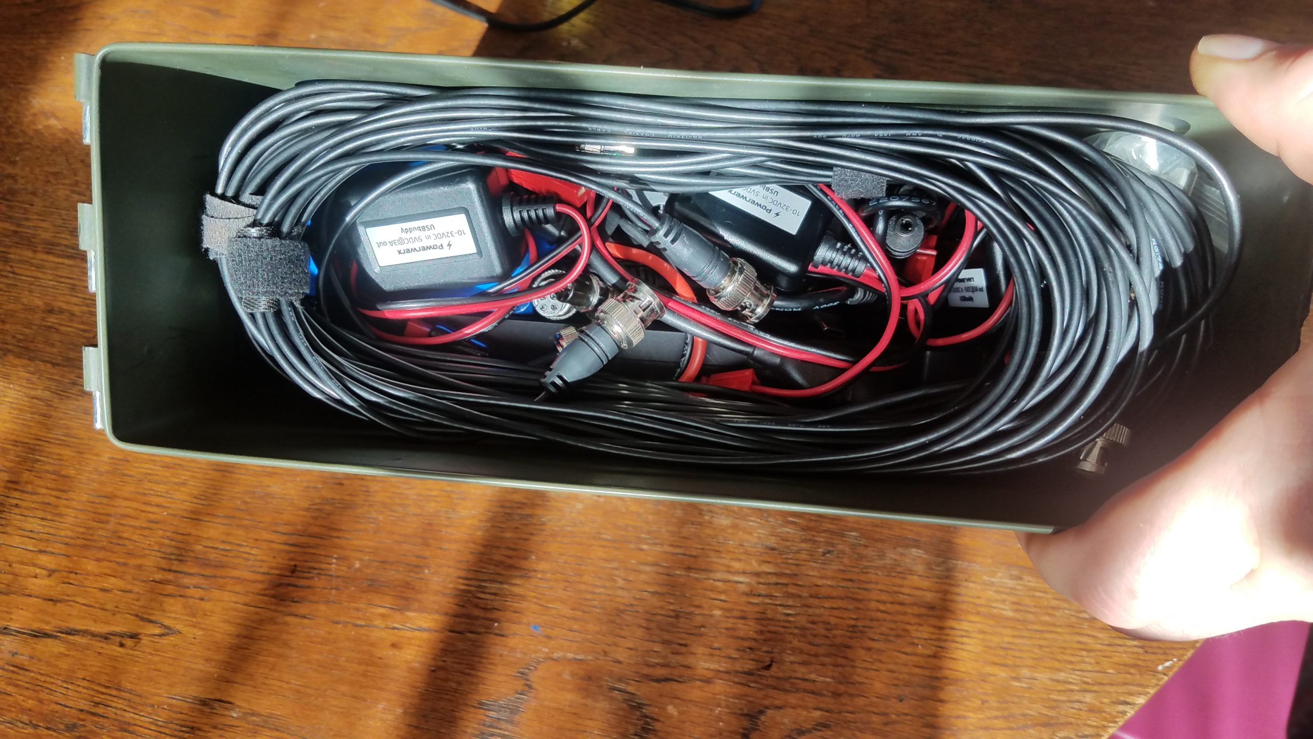
Putting the kit together layer-by-layer is pretty easy. The below photos illustrate how the kit is packed in 3 layers – bottom to top.


Solar power kit
Now that we’ve covered the kit contents let’s talk field charging with solar power! The solar charging system I typically bring with this radio uses one or two 20W Goal Zero Nomad 20 folding solar panels. Those attach to a Buddipole PowerMini charge controller and power meter. Much of this solar charging kit is composed of cables, but it’s designed to be used with a number of my radios, batteries, portable lights, and USB device chargers.
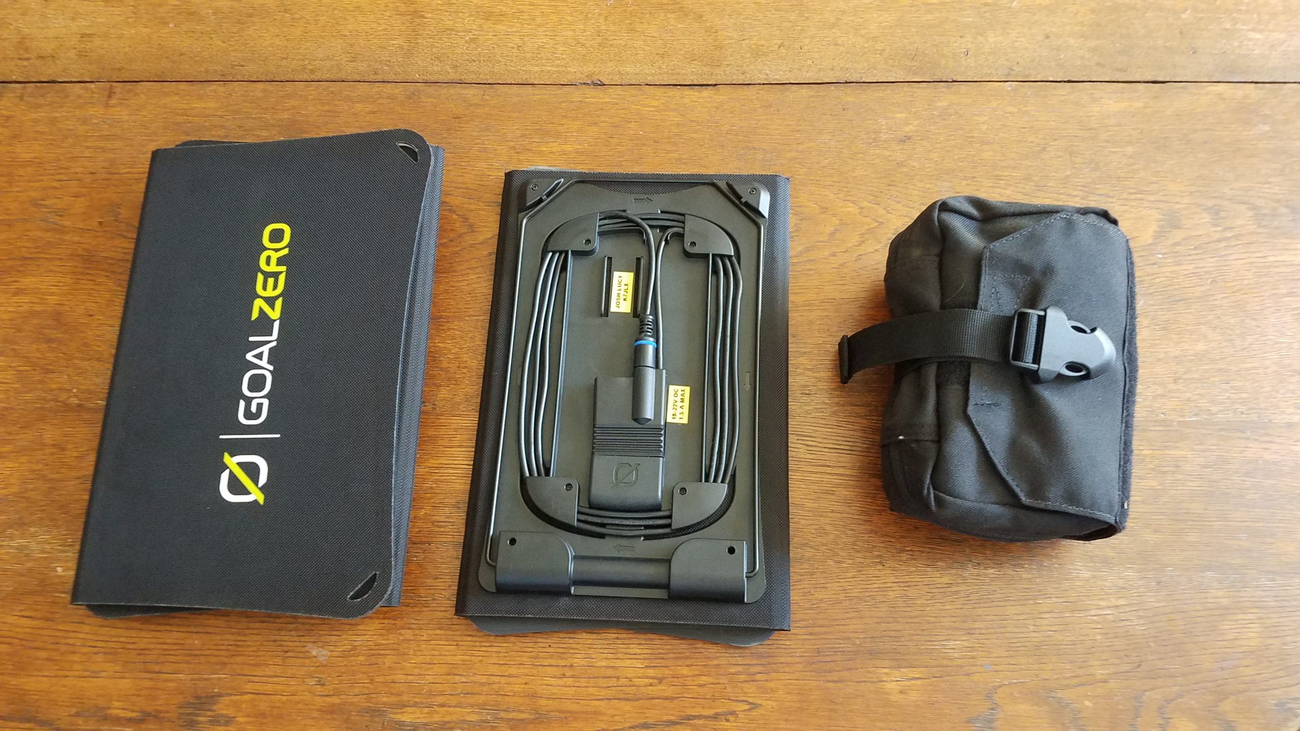
Depending on the deployment I may bring one or both solar panels with the charger kit, or sometimes I’ll just bring the charger kit for power metering to understand how much I’ve drawn my batteries down and at what rate I’m using power. You can check the Buddipole PowerMini’s product page to learn more about it and ways it can be used. In some cases with good sunlight a single 20W panel can provide around 1A (typical max power I’ve gotten from the panels), but in overcast conditions I might use both panels to get 1A peak power. It also might be a good idea to bring both panels to charge at about 2A. It’s especially nice if I expect to charge a phone/tablet and run a radio with a Raspberry Pi if I’m using data modes.
In the above photo you can see the two Goal Zero Nomand 20 solar panels. One of them is staged to show the top view of the panel and the other the bottom view. Each panel has a kick stand to hold itself up at various angles on the ground, cable with an 8mm plug, a USB charging port, and holes in the corners of the panel to suspend them. The Nomad 20s fold open to reveal three solar cells.
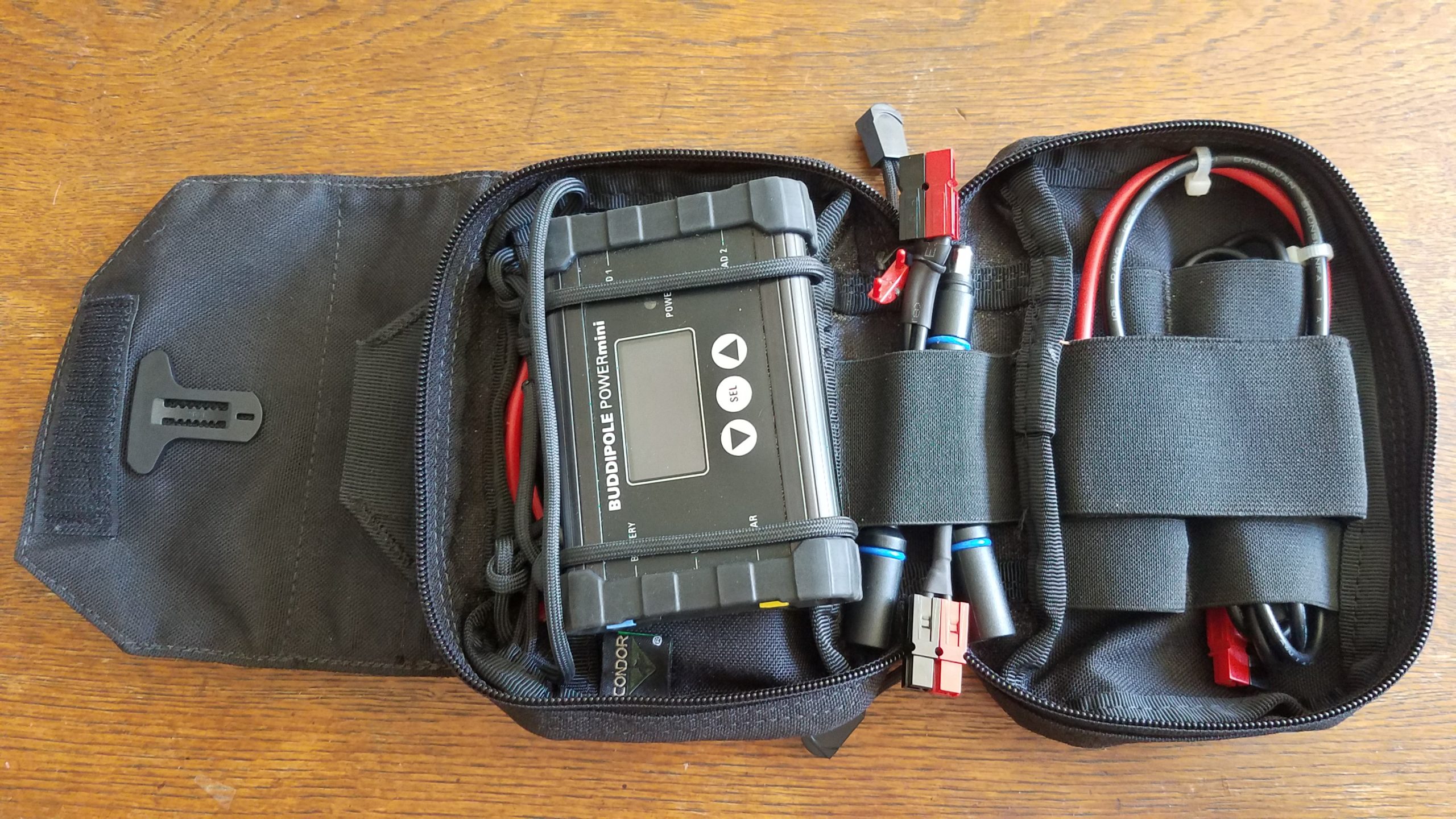

The solar charger kit consists of a Condor MOLLE compatible pouch that has a detachable main pocket which allows you to install and remove the pocket without disconnecting the MOLLE part from the webbing, and also has a loop for easily suspending hanging the kit from something. The kit contains the following items:
- Condor MOLLE compatible pouch w/ paracord loops to hold and suspend the Buddipole PowerMini
- Condor MOLLE compatible pouch attachment platform. This comes as a single unit with the pouch listed above.
- West Mountain Radio PWRNode (4-way Anderson Powerpole connector)
- DIY MC-4 to Anderson Powerpole connector (for a 100W solar panel not pictured here)
- BuddiPole PowerMini
- DIY 2.5″ Anderson Powerpole jumper cable w/10 GA wire (rated for 30A @ 12V DC)
- DIY 6″ Anderson Powerpole jumper cable w/10 GA wire (rated for 30A @ 12V DC)
- DIY 4″ Anderson Powerpole to Goal Zero male 8mm connector pigtail.
- DIY 4″ dual Goal Zero female 8mm plug to Anderson Powerpole pigtail. This allows the two Goal Zero solar panels to be used simultaneously.
- DIY 3′ Female Goal Zero 8mm to Anderson Powerpole cable.
You’ll probably notice there are a lot of seemingly redundant connectors and pigtails in this kit. There’s a reason I carry so many adapters around, and that is to make sure I can run as little cable as possible to achieve connections between system components. Being able to use shorter cables help limit voltage drop, but having the option to use a longer cable to connect the solar panels might mean I can stay in the shade and keep my solar panels in the sun. The short Anderson Powerpole jumpers included in the kit can help me connect to the battery or connect a PWRNode to the PowerMini. The Anderson Powerpole connectors on the side of the PowerMini don’t allow you to connect the PWRNode directly to it, and even if they did you’d lose two of the four connections on the PowerMini side of the PWRNode. In most cases this kit powers the entire radio doing phone and data, a phone and tablet, etc. Most of the time the equipment barely uses the battery while operating during the day and I have a full battery to use at night for the radio and lights.
Antenna hanging kit

Last but not least we have the antenna hanging kit. It’s great to have a radio and a way to power it, but if you can’t get your antenna where it needs to be it’s all for nothing. This part of the kit rounds off the portable radio station. It’s designed to work with a number of wire antennas I have – a Par EndFedz 6m antenna, the Chameleon EMCOMM III Portable, and the Par EndFedz EFT-10/20/40 trail friendly antenna that lives in the HF radio kit. In the case of the trail friendly antenna we require two points of suspension for horizontal dipole operation – the end of the wire antenna and the transformer component. Being in Oregon and setting up my radio station in the region quite a bit I frequently rely on trees as antenna supports, and thus also pack an arborist’s weight as part of my equipment to assist in hanging the line. It adds a lot of weight but is definitely worth it. Using rocks and other tree branches works but definitely comes with snagging risks and the possibility your line will come off of the wight you’re using to get the line up… especially when it comes to rocks. I carry 4 aluminum tent stakes with paracord loops and quick links for attaching line. Those are bound during transport by a piece of paracord I tied together to make the clanking of the tent stakes go away and to keep them from flopping everywhere. There are four aluminum tent stakes in the kit because I might want to anchor my Chameleon EMCOMM III in 3 or 4 spots depending on antenna configuration. I have two 75′ high visibility paracord hanks wound around Chameleon wire winders that can support two ends of antennas that are in a horizontal dipole configuration. Each hank of paracord has a quick link attached for connecting to the ends of an antenna or suspension point, and the arborist’s weight for deployment. I can leave one of the paracord hanks behind if I want to set an antenna up in a configuration that only requires one suspension point like an inverted V. I added a small loop of paracord to the Chameleon wire winders in one of the corner holes to take the weight of the assembly off of the elastic band that wraps the paracord when the hank is being stored or transported. The locking carabiner is used to hold everything together, clip the kit onto something like a backpack, or hang it from a pocket during setup. The specific carabiner I’m using is probably overkill but I had it laying around so I used it. There’s also another loop of paracord attached to the carabiner which acts as a more comfortable carrying handle and for storage by hanging from a door knob.

Kit parts list below:
- Notch 14oz arborist’s weight
- Camp locking carabiner
- Black paracord cut small into smaller pieces for use as a handle, 2x wire winder strain relief loops, and a keeper for the tent stakes (don’t ask me how I figured out how to tie that. I can’t really tell you how I did it except that I did a lot of experimentation.
- 2x Chameleon wire winders
- 6x threaded quick links (4 on stakes, 2 on the 75′ paracord)
- 2x high visibility 75 ft paracord hanks w/ 3M high visibility strip included for working on the antenna suspension at night

Note the paracord attachment point run through the quick links that make sure they don’t come out of the holder or make a bunch of noise. Both loops of black paracord go through the carabiner, but if you remove the attachment point with the quick links from the carabiner it’s easy to just pull the quick links off.

This is a more detailed view of one of the two paracord hanks. Both are set up the same way. The paracord is wrapped around the Chameleon wire winder and is held on the winder using the built-in elastic band which is wrapped around the paracord and secured with the pictured notches. The quick link is attached to the throw/attachment end of the paracord, and the quick link is also attached to the small black loop of paracord to take strain off of the elastic band during transport. This design uses the quick link, black paracord loop, and plastic wire winder plate to take the weight of the assembly when attached to the carabiner.
Connecting it all
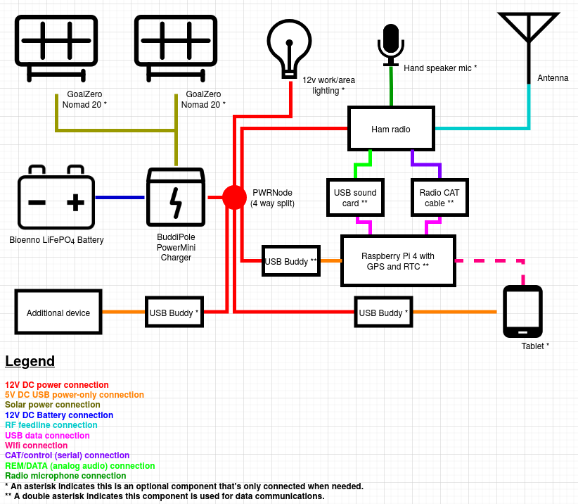
While this isn’t necessarily directly related to the composition of the kits I described above I decided to diagram out how the station is wired up for my typical use and add this section after I wrote the original post. You’ll note that some components are only used in data operations, and some are only hooked up when needed. For example, I won’t need the light unless it’s dark, I won’t want to use the Raspberry Pi unless I’m doing data comms or using the documentation server. In addition I won’t have any of the USB buddies that I don’t need hooked up at any time because they draw power, and unless I want that power to go to something I just won’t use it. If I’m deploying at night and don’t expect to stick around until morning I won’t deploy the solar panels and add the hassle of managing those additional cables and connections. In any case, this is basically how it’s all wired up for my typical deployments. Sometimes I’ll use different components such as a 100W solar panel instead of the 20s, or add a travel router and a USB buddy to the data deployment depending on my situation and available power/battery.
Wrapping it up
So, this is the kits! I don’t always use the trail-friendly antenna with this radio, but it’s what I include in the kit by default. I also use a Samsung Galaxy tablet and sometimes a customized travel wireless router in conjunction with this kit when I do data mode work to interact with the Raspberry Pi 4 in this kit and / or one of the other ones I have set up, but that’s a whole other post.