Starlink Mini as emergency comms platform

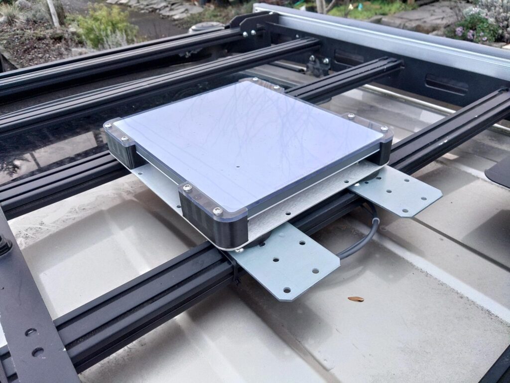
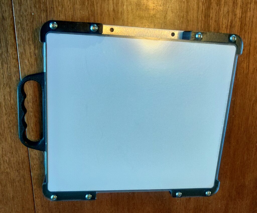
Welcome to another post. This one covers potential uses for the Starlink Mini in an emergency communications, gird down, or other scenario where Internet connectivity is required but unavailable using other means. There are a number of use-cases for it and there are also potential limitations of the device and its use during an emergency. Below is a photo of a Starlink Mini with an aftermarket protective case mounted to ferromagnetic plates (12ga Simpson strong ties) that are bolted to an aluminum roof rack on a vehicle. The screw hole pattern on the strong ties allows easy mounting to the roof rack with its supplied hardware.

What is a Starlink Mini?

The Starlink Mini is a standalone satellite terminal that provides high speed Internet with a clear view of the sky and active service. There are a number of Starlink devices created for various uses. The smallest and most portable offering is the Starlink Mini. It can provide advertised speeds of up to 100Mbps in ideal conditions and the cheapest roam plan for the mini comes with 50GB of data per month at a cost of $50 in the US as of this writing. Service can be paused at the end of the current billing cycle without cost to the user if it’s not needed and can be reactivated at any time. The terminal itself also costs about $450 and is currently on sale in the US. The Starlink Mini doesn’t require an external router like its predecessors and contains its own wifi router and a wired ethernet port. The device is configured and managed with a smartphone app and is designed to be fairly resilient against poor weather conditions. It includes a 15m power cable with 2.1×5.5mm barrel connectors, AC adapter that provides the unit 30v DC, a kick stand, and mast/pipe mounting kit. The Starlink Mini can also be used on a vehicle that’s in motion. The specifications for the unit can be found here.

How can it be used?

There are a number of potential uses:

  • A standard Internet connection that can do everything a regular Internet connection can do: e-mail, social media, chat/voice/video messaging, etc.
  • Using the device to facilitate wifi calling with standard cell phones. This is useful when there’s no cell signal and you need to contact emergency services or call for a tow, etc.
  • Use for Internet-based navigation services such as Google Maps to get live updates on road closures, etc. in areas where there’s no cell service.
  • An Internet gateway for AREDN to provide other users on the mesh with Internet connectivity when other Internet connectivity is unavailable to the mesh or is otherwise saturated.
  • Integration with existing disaster response tools such as Winlink. The Starlink can be used as an Internet gateway for Winlink telnet transport, and its high bandwidth connection accelerate transfers that might be slower using RF Winlink technologies such as packet or VARA. Using a Starlink terminal also removes the need for a dedicated Windows host to continuously run a VARA software modem.
  • Use as an alternative to AREDN when line-of sight to another AREDN node isn’t possible or when adjacent nodes are offline.
  • APRS IGate Internet connection.
  • A backup Internet connection when power is down or there is an Internet outage.

Things it can’t do:

  • Replace GMRS or UHF/VHF communications. This is an Internet connection and doesn’t replace local comms and nets unless every team has one and reliable power for it. Even then it’s not sufficiently portable to communicate with individual teams when cell service is down.
  • Natively connect to AREDN. A router and some configuration will be required to connect the Starlink’s ethernet port to an AREDN WAN port.
  • Work well without a clear view of the sky, active service, and available bandwidth to communicate with satellites. Obstructions like trees, buildings, etc. will prevent it from working, and too many users or too few available satellites for a given area can negatively impact functionality, bandwidth and latency.
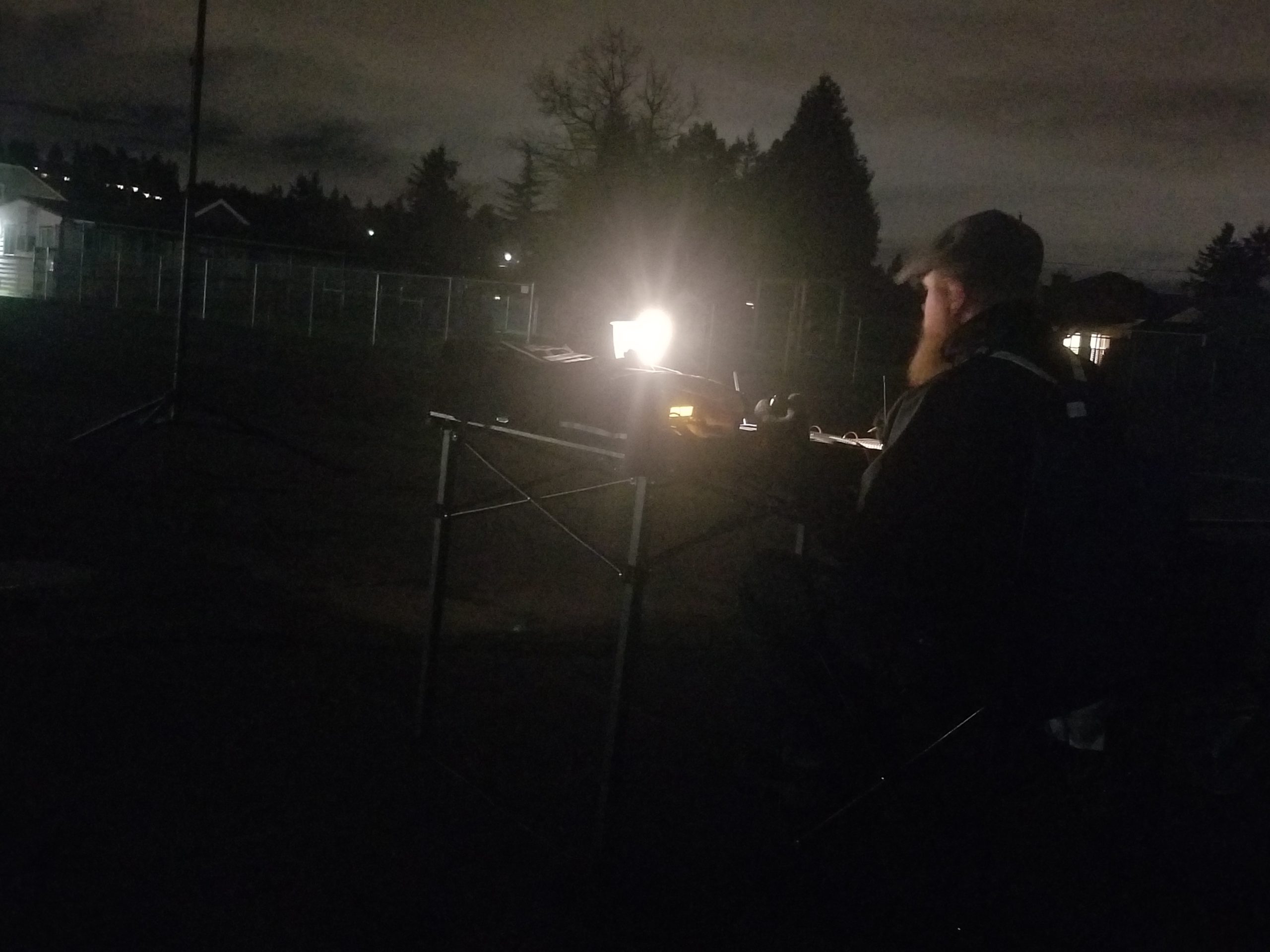
Real life use

I’ve only had the Starlink Mini for a couple months as of the time of writing but have already used it in two situations that weren’t testing or experimentation.

The first real use of the Starlink I had was a long road trip in poor weather (rain, snow, dense fog, high winds) where cell coverage was spotty at various points during the 5 hour drive. I was able to use the Internet connection to maintain contact with others, facilitate navigation, and stream music. On the way back there was an accident that backed up the interstate I was on for miles in both directions, and created hours-long delays. Despite not having cell coverage before I reached the stopped traffic I was able to avoid the wreck because Google Maps got a real-time alert and routed me around the accident using an alternate route automatically.

The second real use of the Starlink Mini was allowing me to continue working during an Internet outage. I was able to work normally including video calls and meetings after setting the unit up outside and connecting it to my network in a box (boost converter and router) that provided strong wifi coverage in the house. Even if I had lost Internet connectivity and power I could have run the network-in-a-box and Starlink on battery. See photos below of the network in a box.

Adapting the unit to work without AC power

The first problem to solve with the unit is its reliance on AC power. You can connect the unit to an inverter or AC generator for power, but using a generator requires a steady supply of fuel and an AC inverter consumes a lot of power that’s used to boost your 12v DC batteries to 120v AC only to be downconverted to 30v DC in the end making it less efficient than a single step of boost conversion. I chose a boost converter that boosts the power from 12v DC to 24 DC and can provide up to 10A of current. While some power is lost in the boosting process this is much more efficient than a large voltage boost and AC conversion followed by a second downconversion to 30v DC. The 24v boost converter and that works with the 15m DC cable included with the kit.

It’s worth noting that the power cable is a small and there’s too much voltage drop over the length of the cable with 12v to run the unit as the required amperage at 12v is too high for the cable gauge, and the voltage is too low to power the unit. The higher voltage provided by the boost converter requires less amperage to provide the same wattage to the Starlink. Ohm’s law (Pwatts = Iamps * Vvolts rewritten as I = P / V using variable isolation) tells us that at a reference power level of 25w and 12v the small gauge cable has to handle about 2.1A over 15 meters, and that doesn’t consider voltage drop which prevents the device from functioning properly [25w / 12v = ~2.1A]. The same reference power level (also excluding voltage drop) at 24v requires the wire to handle about 1.1A [25w / 24v = ~1.1A]. Shorter cables such as the 5m aftermarket cables can run the unit on 12v but it does get fairly warm running on that voltage even with the shorter cable length and I wouldn’t recommend that especially in a warm environment as it may damage the Starlink Mini.

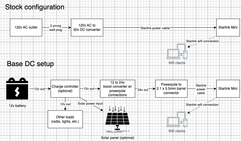
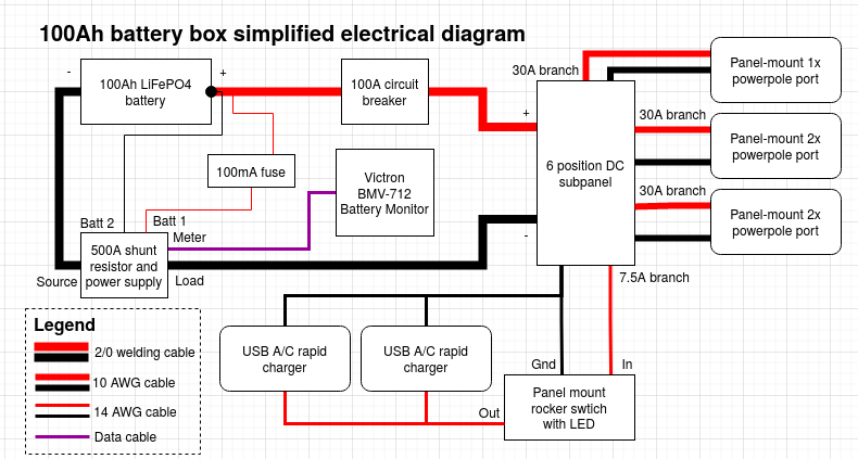
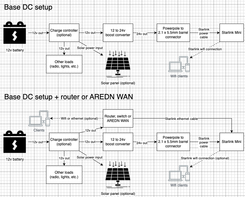
Power connection block diagrams for stock configuration and my base DC configuration

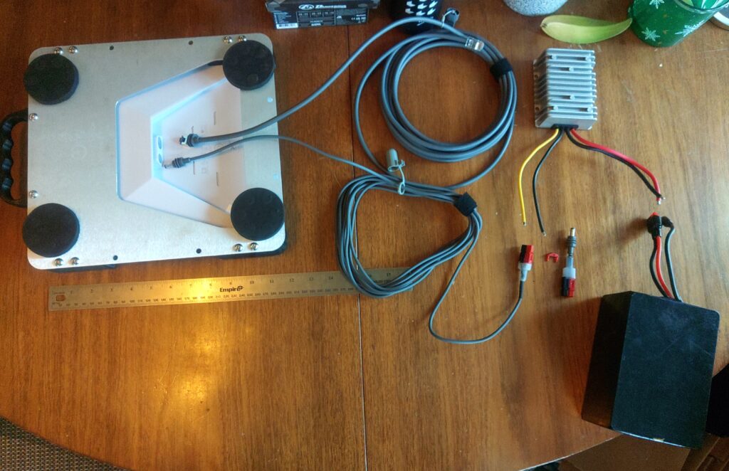
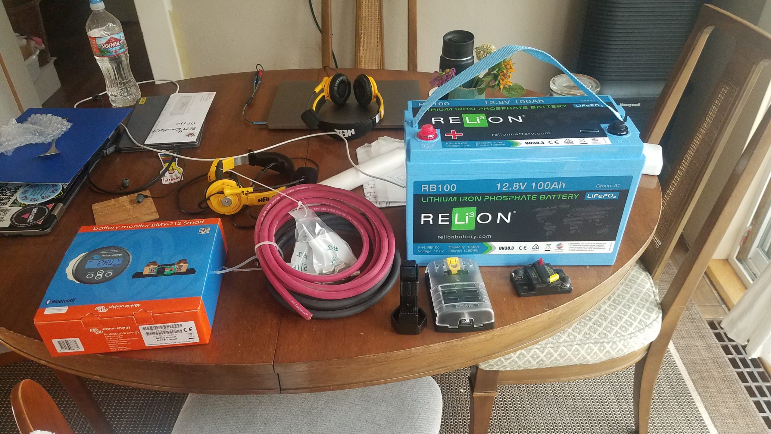
Exploded view of connections made in the base DC setup with the optional ethernet cable represented. From left to right, top to bottom is the Starlink Mini upside down showing the connection points, an ethernet cable with nothing connected to it, the DC power cable, 12-24v boost converter, and battery. It’s worth noting that the boost converter pictured here is for another project and is much larger physically and in terms of power capacity (20A) than the one used by me to run the device (10A) in the field and is there as an example.
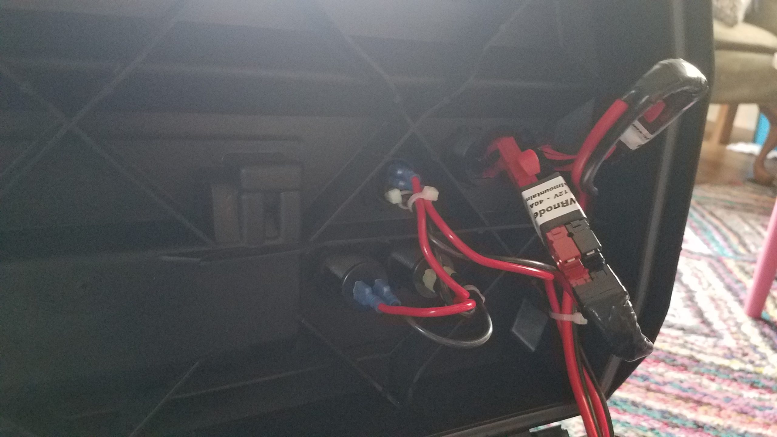
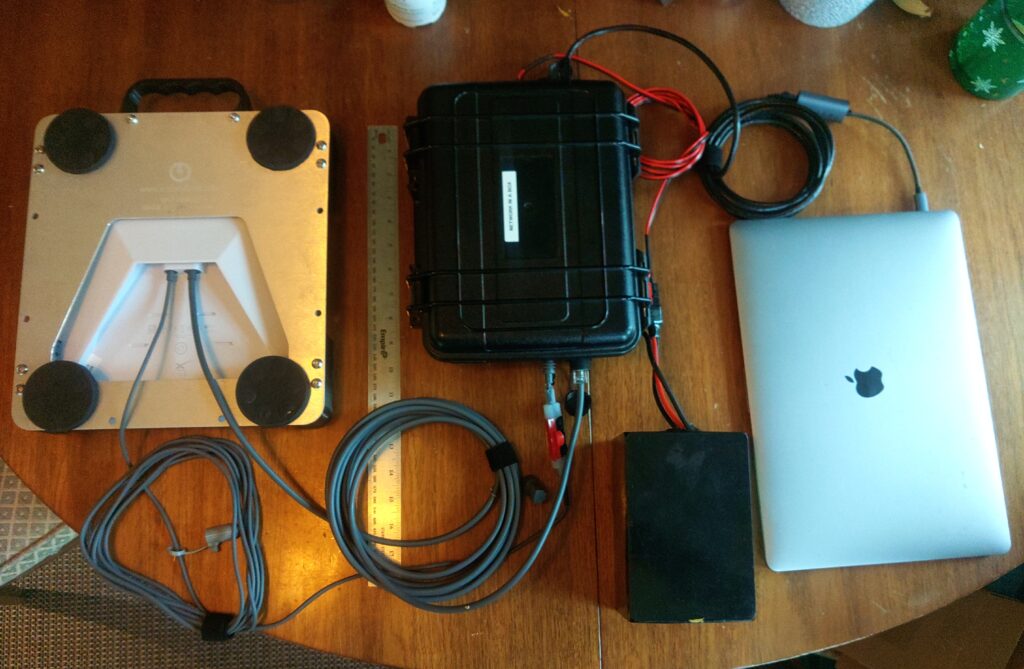
Network in a box

The network in a box is my solution for making the components that run the Starlink from a battery more compact, portable, and protected from dust and rain when in transit. Having all that set up ahead of time reduces the amount of time needed to fumble around making connections under duress or in adverse conditions and reduces the likelihood of human error causing damage to various components given the differences in voltage between the Starlink Mini and all other components. After dust and rain caps are removed from the ports it is no longer protected from the elements. There is a section that details the network in a box’s wiring, ports, etc. near the bottom of the post. The picture blow shows the system connected to power the Starlink, connect ethernet to the router included in the box, and has the optional ethernet connection to the laptop hooked up. Another advantage of having a separate network in a box is that the router running OpenWRT is more configurable than the Starlink Mini itself and supports features like firewalls and VLANs. These features can be important when integrating the Internet connection with an AREDN mesh node.

Optimizations, accessories, and considerations

Power consumption and snow melting capabilities

The unit tends to use about 25w of power at the unit (not including power used boosting the voltage) while running without the snow melt system running. I’ve intentionally disabled the snow melt functionality to prevent unwanted spikes in power usage. Most scenarios I’ll use the unit in involve me being outside or near the unit so clearing snow from the unit by hand shouldn’t be an issue. With the additional thickness of the protective polycarbonate layer and small air gap between the two I suspect the snow melting functionality would be less effective anyway.

Cable kits and cabling considerations

I have two power cables for the unit – one aftermarket 5m cable and the 15m cable included with the kit. The 5m cable is more efficient and has a lower voltage drop than the 15m one and can be used when the unit doesn’t need to be far from me to get a clear view of the sky. It’s also nice to deal with only 5m of cable unless you actually need the 15m length to fit your situation. These power cables are 2.1 x 5.5mm barrel connectors with a center pin positive configuration with weather resistant boots on both ends. I did splice powerpole connectors inline with the Starlink DC cable so I can connect directly to a 24v boost converter that has powerpole ends installed if necessary. It removes the need for multiple adapters in some situations, but allows you to connect to the native barrel connector in others.

In order to connect the unit to AREDN or any other network you might want to run that can’t run as a wifi client you’ll have to purchase a special weather hardened ethernet cable that has a boot that seals the port on the unit when the plug is removed from the port. I have an aftermarket 5m cable to match the power cable’s length and purchased a 15m cable from the Starlink website for about $30. This pairing of cables enables me to optionally connect the unit to a router or switch and can allow me to move the wifi access or cabled access closer to my work area which might be necessary if the position of the Starlink unit prevents a reliable wifi connection.

The official and aftermarket Starlink ethernet cables I purchased have proprietary RJ45 ends with a weather resistant boot that protects the jack from water and dust ingress. I ended up cutting one end off of each ethernet cable and installing a standard RJ45 end for compatibility with standard ethernet jacks found on most consumer routers and switches.

Protecting the unit from adverse conditions and adding additional mounting capabilities

While it’s not explicitly necessary to deploy the Starlink Mini physically hardening the unit with an aftermarket case could also be useful in some situations and has some advantages, but has costs in terms of additional bulk, weight, and safety considerations in my configuration. The surface of the satellite terminal that faces the sky can be scratched, gouged, or otherwise damaged by branches or sharp objects. Third party manufacturers make cases for the unit that allow it to operate in rougher conditions than it was designed to and add some advantageous security properties along with additional mounting options.

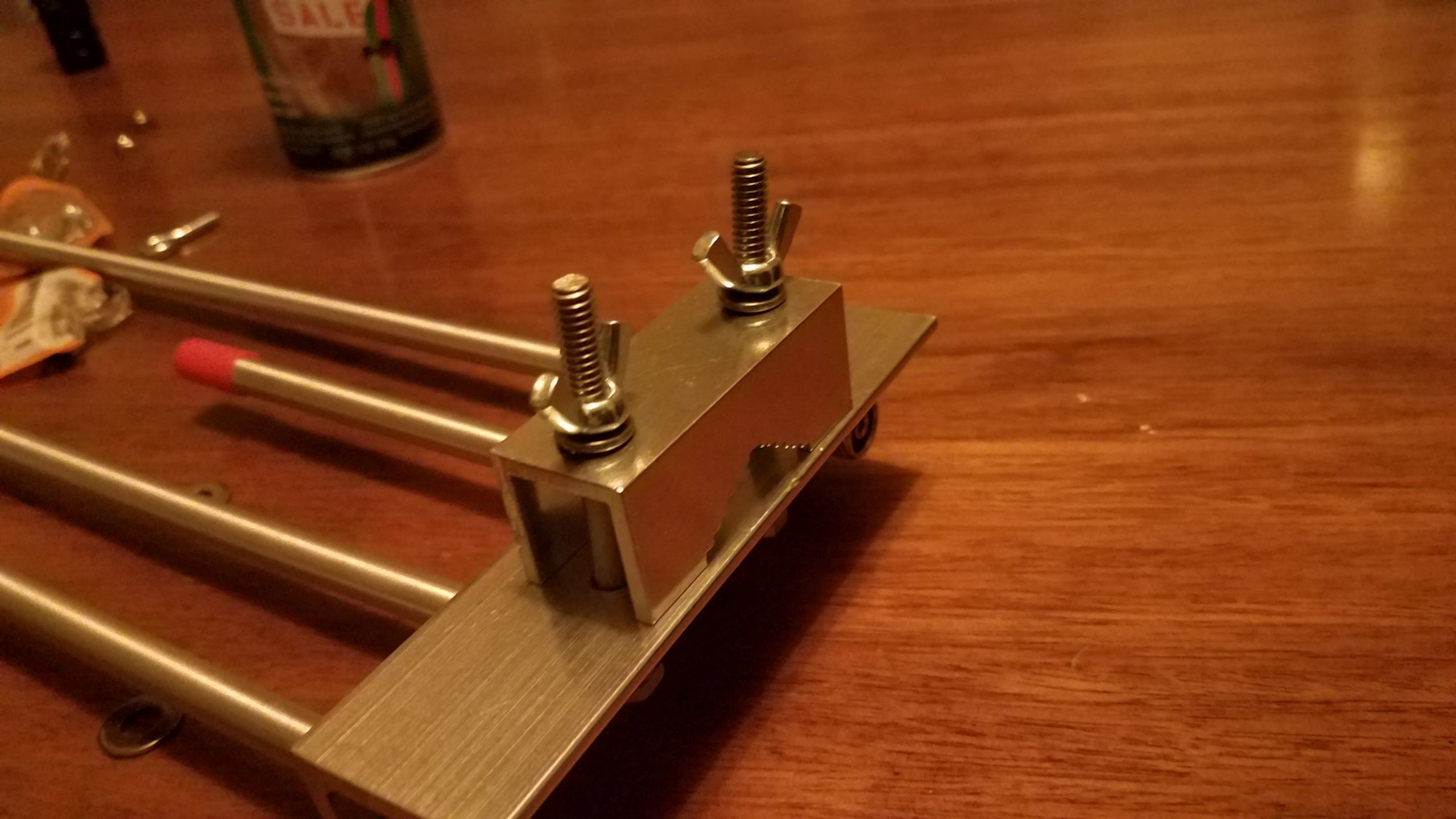
The case I purchased from Striker Fabrication has a handle, aluminum baseplate, and polycarbonate lid for the top of the unit. This allows me to mount it to my vehicle when offroading or on the highway as branches might sweep the unit or debris may strike it resulting in damage to the sky-facing surface. I added four 65 pound magnets with M6 threaded posts and lock washers to the corners of the unit that allow me to mount it to any magnetic surface such as a vehicle roof or hood. The holes I used to mount the magnets can also be used to bolt the case to any other permanent or semipermanent mount point using M6 screws. The aluminum plate under the case is compatible with the mounts that come with the Starlink Mini so it can be placed on a pole or on the ground with the included kickstand without needing to be removed from the case.

I can also loop coated wire rope through the aluminum and roof rack and secure it with a pad lock to ensure that a branch strike won’t sweep the unit off the roof of my vehicle entirely while in motion. It also acts as a theft deterrent for when the vehicle is unattended. I have two other pieces of coated wire rope that are 2.5 feet short of the full length of the power and ethernet cables to make theft of the deployed unit more difficult and to provide strain relief if the cable is pulled or tripped on when deployed on the ground. If the coated wire rope is anchored to a secure point on the terminating end a trip or pull on the cable is less likely to result in the power and network cables from being ripped from the Starlink Mini or attached power supply and network equipment. A pulled network or power cable can damage other equipment such as batteries, network hardware, or laptops by pulling them over or off of elevated surfaces. The Starlink unit will hopefully be the part that is harmlessly dragged by the coated wire rope due to its relative light weight and the other end of the cable being secured. The choice of coated wire rope was made because of its relative strength and light weight. The coating on the wire rope prevents scratches on painted surfaces, allows it to slip past snag points more easily when pulled, and aids in corrosion resistance.

Magnet safety warning: The four 65 pound magnetic feet provide a total of 260lbs magnetic pulling force. These will unexpectedly stick to metallic objects, pick up sharp bits of metallic grit and filings that can damage paint, and they will stick to metallic objects in your pockets or in your environment while being carried. Be aware of your surroundings and exercise caution. The magnetic mounts can also cause the case to crush your fingers when the case sticks to a metallic surface. Don’t ask me how I know. It’s worth noting that with this configuration it can be difficult to remove the device from a surface that it’s stuck to. Exercise caution when using powerful magnets – especially when handling the unit, sticking it to a surface, or removing it from something it’s stuck to. When it comes loose it does so quickly and you can unintentionally throw the unit when it releases. Again, don’t ask me how I know.

Factors effecting operation and Internet bandwidth

Internet connection speeds vary due to a number of factors including the location of the unit and whether or not it has a clear view of the sky according to its specifications, the number of users connecting to the satellites the unit is also using, and wifi connection strength.
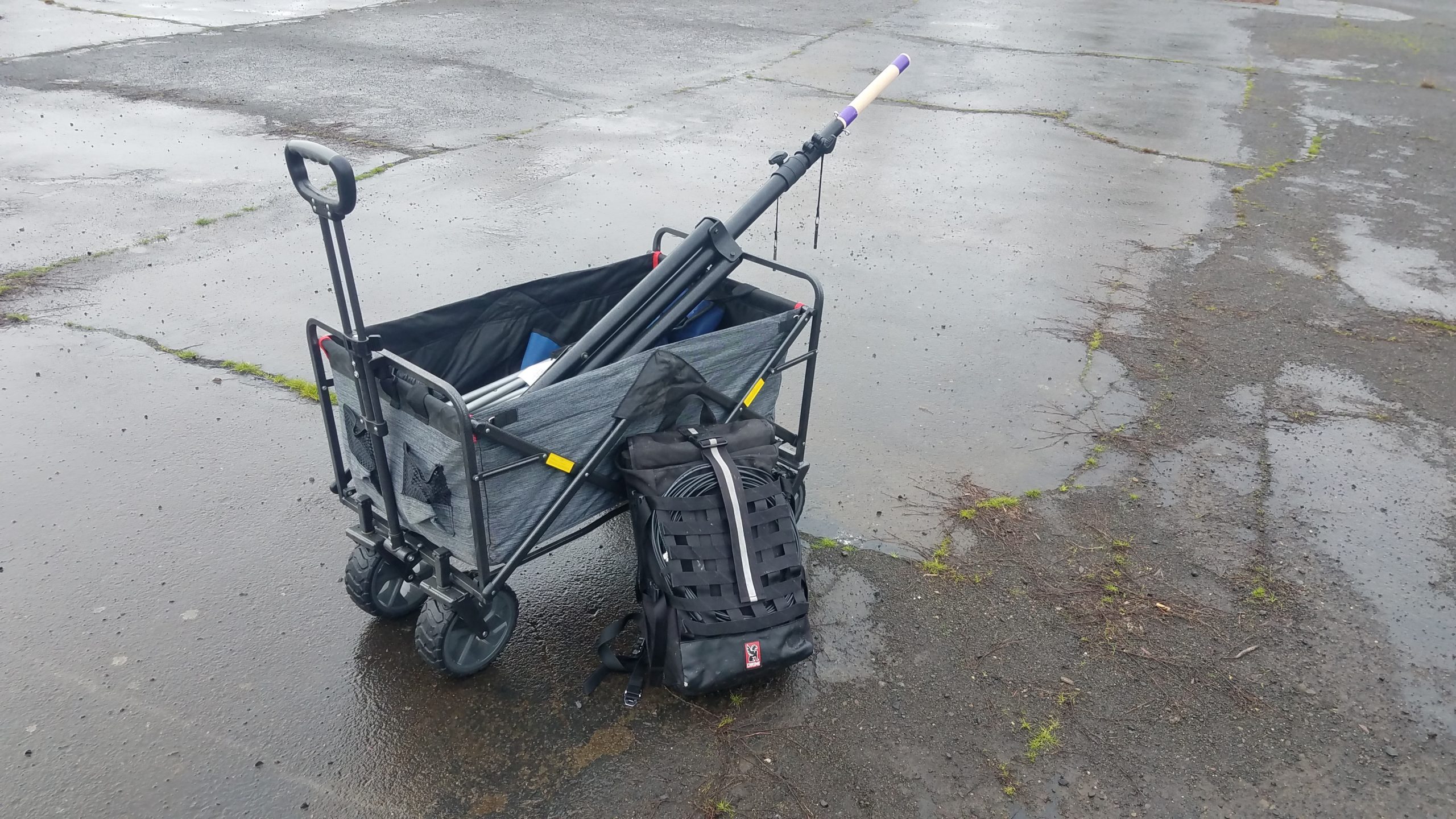
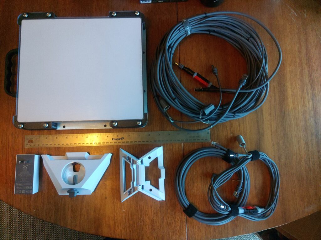
Full kit photos

The following photos show the full kit. Most components of this kit are fully optional. The only real requirement to run the unit is the 12-24v boost converter and associated connections along with an activated Starlink Mini and a clear view of the sky. The picture shows the 15m cables power and network cables that are zip tied together every 18 or so inches since they’re almost always used by me at the same time, but the ethernet end doesn’t have to be connected if there’s a reason not to. The 5m cables are separate because I can usually use the Starlink Mini’s wifi at close range and handling more cable isn’t usually necessary but I have the option to deploy the second cable if needed. This kit includes aftermarket water + dust resistant caps on the Starlink end of all cables to protect the cables from water and dust during deployment and breaking down in adverse conditions. The bottom row on the left shows the AC power adapter, pole mount, and kickstand when opened, but not attached to the bottom of the unit. The pole mount and kick stand snap into the underside near the network and power cable ports and the enclosure is fully compatible with the mounts as well.

Base configuration and added router / AREDN node

The following block diagrams depict a basic DC power setup with optional solar and battery charge controller as well as a configuration that connects the Starlink Mini to a router or AREDN node. Since AREDN nodes are functionally routers the connection principals are basically the same. See the above photo of the network in a box setup to see what the wiring looks like with a connected router.

Network in a box detail and photos
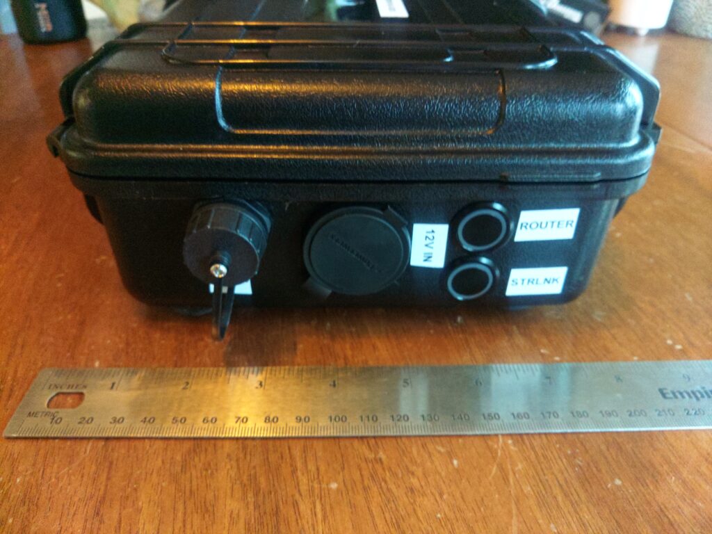
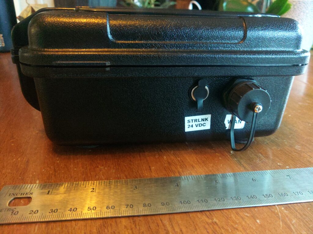
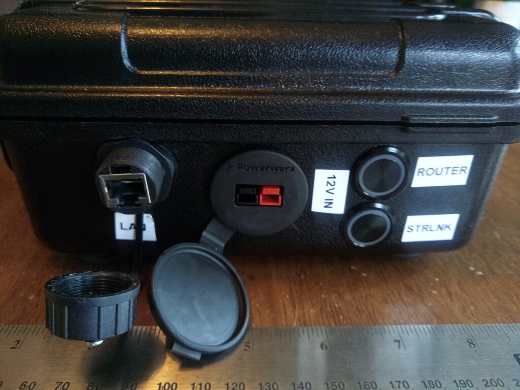
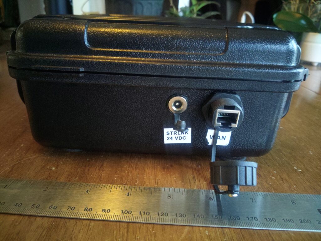
Exterior detail

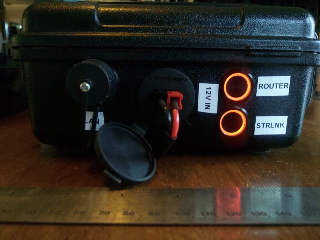
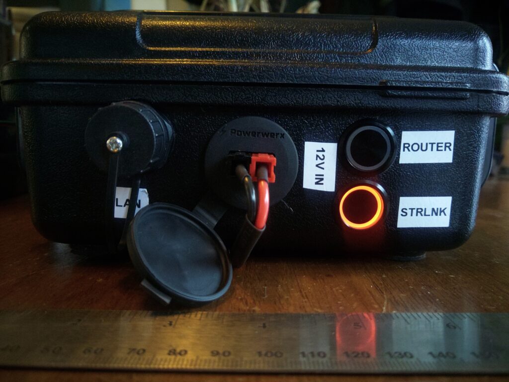
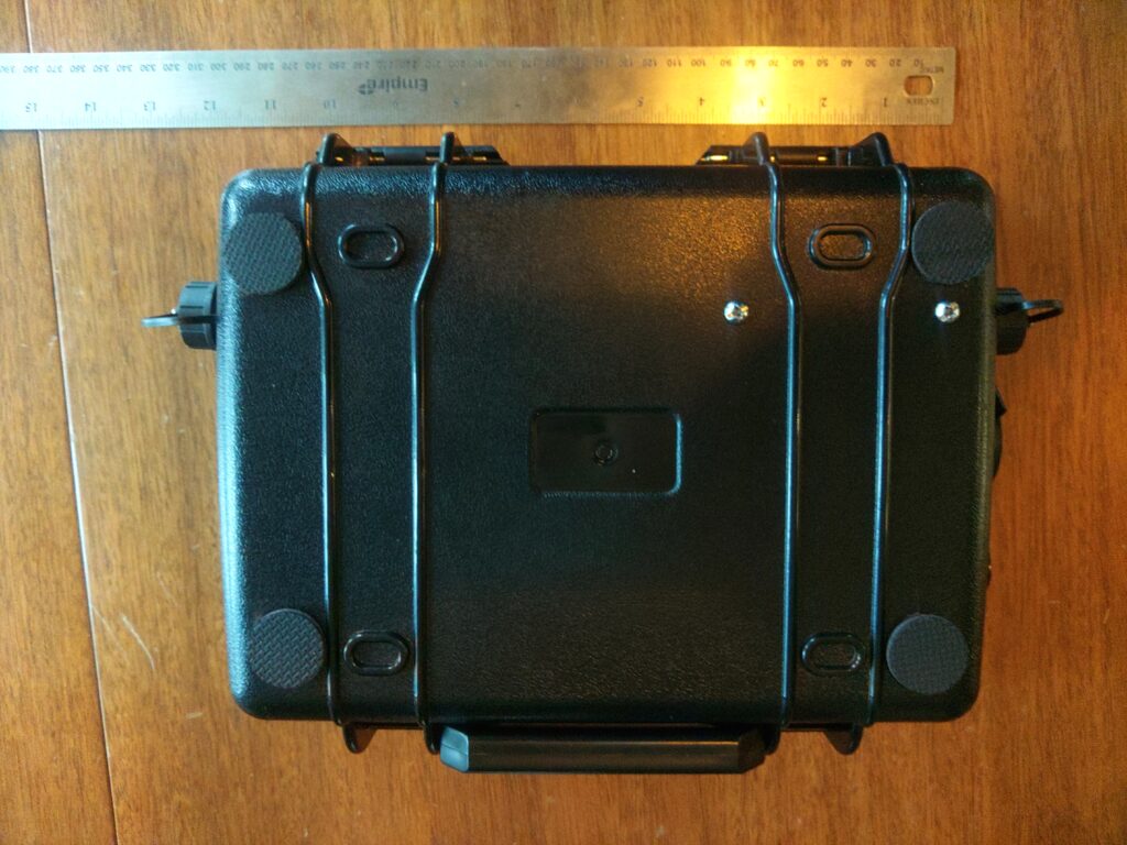
The gallery below shows the exterior of the enclosure including ports and power controls. As noted previously this unit has port covers designed to protect the system from dust and moisture in transit. Once the ports are opened the unit is vulnerable to dust and water ingress so it requires some care after being deployed. The bottom of the unit has non-slip pads stuck to it because the enclosure’s bottom is slippery and there is a chance the screws that hold the boost converter could scratch surfaces so those non-slip pads also provide a degree of separation between the screws and the surface the unit is sitting on.

Power is provided by a single powerpole connector wired in a right-hand-red configuration, and power to various components is controlled by two pushbutton switches with LED power indicator rings. These physical switches are installed for easy control of loads and to prevent parasitic power draw when components shouldn’t be running.
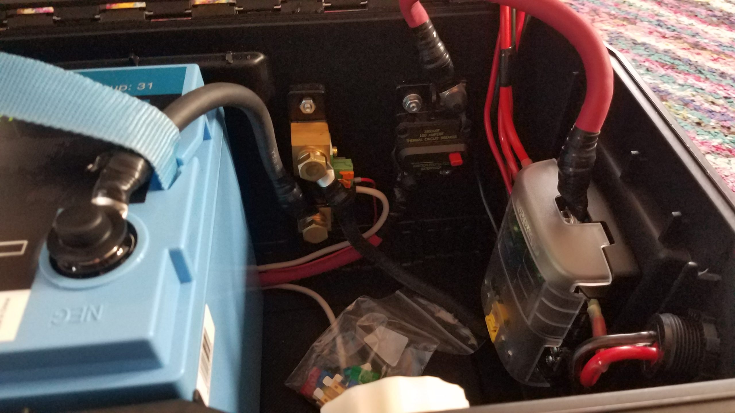
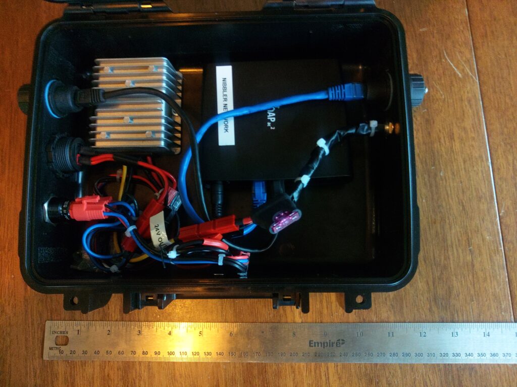
Interior detail

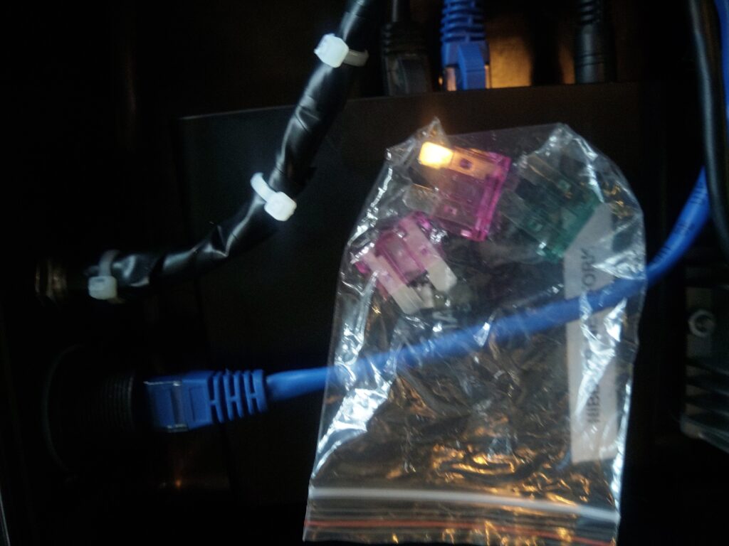
The inside of the enclosure is shown below. The major components are a DC 12-24v boost converter, a Mikrotik hAP2 router running OpenWRT, an open source router firmware, switches, fuses, power wiring, and network connections. The unit includes a bag of spare 1A and 3A fuses that are stored inside the case for field repairs. The router is connected to the bottom of the enclosure using velcro so it can be removed as needed. All power connections in the case are also powerpole so in the event some component fails and needs to be replaced, bypassed, or reused elsewhere on the fly there’s minimal effort, tools, and wire splicing required to make changes.

Starlink Mini network engineering details

The Starlink unit is configured from the mobile app, but the base networking characteristics of the unit are as follows:

  • The Starlink Mini has a built-in router and dual-band wifi access point as well as a weather-hardened proprietary ethernet connector that supports provides 10/100/1000Mbps ethernet. This connector is a modified RJ45 jack wired using the EIA 568B standard. The official Starlink ethernet cable is outdoor rated Cat6 shielded twisted pair.
  • Starlink service provides native IPv4 and IPv6 capability.
  • There are 2.4 and 5Ghz wifi networks generated by the unit itself and these can be disabled or split into different SSID based on frequency if required for certain devices that have issues selecting the correct network.
  • The unit is configured to hand out IPv4 and IPv6 addresses using a local DHCP server runing on the Starlink Mini when it’s in the default operating mode (not in transparent bridge mode).
  • The default IPv4 address space is 192.168.1.0/24 and the built-in router uses 192.168.1.1 for its address and the default gateway.
  • I don’t think there is any web UI to configure the router on the Starlink Mini. This isn’t the case with other Starlink products I’ve worked on. The mobile app or Starlink website is required to configure the Starlink Mini.
  • Access to GPS location, telemetry data, and configuration endpoints are available via gRPC endpoints hosted on the Starlink Mini unit. These gRPC endpoints may also be the mechanism that the app uses to configure the device. See Sparky8512’s project for example code that interacts with the gRPC endpoints.
  • Unlike its predecessors it can’t be powered using power over ethernet. The DC power cable is required for the Starlink Mini to power up.
  • The unit can be set up in transparent bridge mode and any wired device connected to it is required to run its own DHCP client to get a WAN address from the upstream Starlink network. In order to switch back from transparent bridge mode the unit will have to be factory reset using the reset button on the under side of the unit.
  • All wired and wifi hosts connected to the unit are dropped onto the same subnet and can communicate with each other directly. There doesn’t appear to be any client separation inside the LAN.
  • The advertised WAN bandwidth is up to 100Mbps but I and others have seen speeds in excess of 100Mbps in certain locations and conditions.

100Ah battery box build

Ok, so this is a big one. I wanted to build a battery box that could keep me going a few days without being able to charge while camping and/or operating. I also wanted accurate power accounting and the ability to understand my power consumption and have alarms when usage exceeds specified thresholds, providing the opportunity to either adjust usage or in an emergency not be surprised when I drop out. I also wanted to design the system for maximum flexibility when it comes to charging and connecting loads. Most commercially-available systems that met capacity and power needs were designed around inverters and larger 30+ volt solar panels that were designed to mount on structures or large vehicles like RVs or vans rather than the smaller and more portable 18v open circuit foldable panels that are used more commonly for my purposes. Having a wider range of panels that I can use is better because it would be good to charge from either so not building in charging was ideal. I also found the options for high-amperage DC connectors lacking in many pre-built options. Some units would have one or two 25A outputs, but those are at the max current range some of my radios will draw at full power. I wanted some breathing room current-wise. In the event I wanted to operate one of my bigger radios at full power I’d rather not risk burning a fuse out or damaging my power source – especially in the field while I’m relying on it. It’s also nice to have many connectors available on the source which eliminates the need for a bunch of splitters. None of the commercially-available options I evaluated provided more than two high amperage connectors. Finally, I wanted a couple USB fast chargers for my and my partner’s devices which many commercial options provided, but they’d typically provide a single fast charging port.

I took some inspiration from a Powerwerx box that a fellow ham and NET team member Laura, KI7ZZQ purchased. That battery box was designed to accommodate a 50-70Ah battery which wouldn’t physically fit any of the 100Ah batteries I had been considering during the design phase, but it provided me a rough template I could build from in terms of layout. As with that box just including power distribution and monitoring in the box was a way I could reuse existing systems I have that perform well without having to buy more of those components. Buying a bunch of new parts is pretty expensive so not including more core devices in the box is definitely a plus.

This was not a cheap project, but I think it’ll be worth it.

Theory and design

By selecting a 100Ah battery I get 80Ah of usable power from the system without significantly decreasing the battery’s lifecycle. Using LiFePO4 batteries instead of lead-acid means I get an additional 30% depth of discharge without the destructive effects of discharging to 50%… The LiFePO4 battery I selected also weighs 26lbs. A similar capacity lead acid battery would weigh a lot more and probably require a much sturdier and expensive enclosure. Another advantage of LiFePO4 batteries is the lack of battery memory – that is to say the useful lifetime of a battery isn’t diminished by leaving it in a partially-charged state. Some battery technologies suffer from that problem which is a problem if you’re in a situation where you might not be able to completely recharge the battery completely during use. As far as parts go I wanted to attempt to source the parts I didn’t already have from a variety of vendors… I had a preference for smaller and more local vendors, but that didn’t work out 100% of the time. The enclosure (tool box) and a 1 1/8″ hole saw are two examples of where that didn’t work. The bill of materials will list the source of each component.

So let’s start with the system design itself. There are a few core components that I knew I’d probably want from designing a bigger high amperage system when my partner were considering purchasing and building out a van for camping/touring. The core parts that everything else would be designed around are:

  • 100Ah LiFePO4 battery
  • Reliable battery state and power usage monitoring capability
  • Battery disconnect for safety and preventing parasitic loads from draining the battery
  • Circuit breaker for the battery to prevent damage to components or fires
  • DC subpanel to split out and protect branch circuits
  • Two switched USB rapid chargers.
  • Flexible charging – AC-to-DC chargers (wall socket, generator), solar panels of various types, and DC-to-DC (vehicle, independent DC power supply, DC generator outputs)

Those components are roughly connected and arranged as follows. Chargers can be connected to any of the powerpole connectors listed below, and so can loads. The only loads that wouldn’t be connected to powerpole connectors are devices directly connected to the built-in USB A/C rapid chargers. You’ll notice there’s a power line running from the battery to the 500A shunt resistor and power supply that feeds the Victron BMV-712 through a 100mA fuse, bypassing the circuit breaker which also doubles as a battery disconnect. That’s intentional as the BMV-712 requires constant power to track battery state and if powered off it will lose its zero-point configuration. This is the only parasitic load that isn’t switched in this system apart from the BMS built into the battery, but it’s required to get accurate battery status so I compromised.

Block diagram showing electrical connections between a battery, shunt resistor, circuit breaker, DC subpanel, USB chargers, and power connectors.

Materials / parts

High amperage and distribution components
DescriptionQtyMake and modelVendorLinkNotesTool?
100Ah LiFePO4 battery1Relion RB100LightHarvest SolarHereN
Red #2/0 welding cable, 10′1?HereN
Black #2/0 welding cable, 10′1?N
100 amp circuit breaker *****1Eaton 285100FHereN
6-position 100A DC subpanel1BlueSea 5025HereN
Hammer-type crimping tool1TE(?)HereY
Battery monitor1Victron Energy BMV-712HereN
#2/0 Lug Ring Terminal (5/16″) *3?HereN
#2/0 Lug Ring Terminal (3/8″) *3?N
#2/0 Lug Ring Terminal (1/4″) *5?N
10A LiFePO4 14.6v battery charger1Bioenno Power BPC-1510ABioenno PowerHereDedicated AC-to-DC chargerN
Tool box1Dewalt DWST24082 One Touch Tool Box, BlackHome DepotHereUsed as enclosureN
#10-24 3/4″ cap screws and nuts (x8?)1?HereN
#10-24 1″ cap screws and nuts (x6?)1?HereN
#10-24 Bonded neoprene washer (x4)3?HereN
1 1/8″ hole saw1?HereUsed for Powerwerx panel mount devicesY
Panel mount powerpole socket (x2)2Powerwerx PanelPole2PowerwerxHereN
Panel mount powerpole socket (x1)1Powerwerx PanelPole1HereN
USB A QC + USB C PD charger, panel mount2Powerwerx PanelQCUSBCHereN
Bonded 10GA stranded copper wire, 25′1Powerwerx Wire-RB-10-25HereUsed for 30A branch circuitsN
Bonded 14GA stranded copper wire, 25′1Powerwerx Wire-RB-14-25Used for 15A branch circuitN
Powerpole to “cigarette lighter” adapter1Powerwerx SOC-PPHereStored in the enclosure as an adapterN
4-Way powerpole splitter2West Mountain Radio PWRNodeHam Radio OutletHereUsed as splitters for the 2x panel mount powerpole socketsN
Panel mount rocker switch w/red LED, 15A max1Powerwerx PanelSW-RedHereN
15/30/45A red powerpole housings6Powerwerx PowerpoleCaseHereN
15/30/45A black powerpole housings6N
Powerpole retention clips6N
45A powerpole contacts22N
Powerpole crimper1Powerwerx TRICrimpHereY
F2 blade connectors, 12-10GA3???N
F2 blade connectors, 16-14GA4???N
Lug ring terminal, 12-10GA6???N
Lug ring terminal, 16-14GA2???N
7.5A ATC blade fuse *3???N
30A ATC blade fuse *5???N
Assorted ATC blade fuses6???Included in enclosureN
Packing foam **????N
Electrical tape ***1???N
1 1/4″ bolt and flange nut ****1???N
Zip ties5???N
3/16″ (?) drill bit 1???Used to drill holes in plastic fins in toolbox for zip tiesN
Electric drill1???Used w/hole saws and drill bitsY
2″ hole saw1???Used to drill a hole for the Victron BMV-712 panelY
Phillips screw driver1???Y
Metal shears1???Used to cut #2/0 welding cableY
Diagonal cutters1???Y
Socket wrench1???Y
?mm socket1???Used for shunt boltsY
?mm socket1???Used for battery terminal boltsY
?mm socket1???Used for #10 nutsY
?mm socket1???Used for DC subpanel 100A contacts
Needle nose pliers1???Used to help pull wires, tighten panel mount nutsY
Claw hammer1???Used w/ the TE hammer-type crimping toolY
Pocket knife ******1???Y

Legend
? Can’t remember/unknown
— Same as above
* Includes spare(s) or extra(s)
** This is small-cell plastic foam used as packing to keep the battery from moving around a lot
*** Used mostly to bind wires and as extra insulation on the #2/0 ring terminals. Also used to physically shore connections up due to gaps in wire jacketing or potential stress points from bends.
**** Used as insurance to hold the toolbox closed in case the latch is opened unintentionally
***** Doubles as a battery disconnect switch
****** Used to clean plastic burrs left from the hole saws and to cut the jacketing on the #2/0 cable in preparation for crimping

Assembly

This was done in a a couple phases – in part because I was waiting for things to come in the mail, and in part because I sort of “winged it” building this out in terms of mounting components to the enclosure. The first thing I did was pick locations for each of the high amperage components: the battery, BMV-712’s 500A shunt, 100A circuit breaker, and the DC subpanel. I made sure to allow for enough space to run cables to and from each component before drilling holes for them. The battery was pushed to the left side of the tool box. This makes it a bit awkward to carry but creates enough space in the right side to mount everything.

Once I found a good placement for the components that required mounting I just drilled holes in the enclosure using the components as a template. For each component I drilled an initial hole and inserted one of the #10-24 cap screws in the hole to hold it. I then drilled out a second mount and placed another bolt in it. After I’d placed all the components and got the holes drilled for them I added the #10 bonded washers with the neoprene side on the outside of the enclosure. To minimize jagged edges from threads on the outside of the enclosure I put the phillips end of the cap screws on the outside as well. The nuts and lock washers were placed on the inside.

The next step was to route, measure, and cut the high amperage #2/0 welding cable between each component. I did a dry run of the cable from component to component and cut each piece to length. I ran a piece of from the negative battery post bolt to the BMV-712 shunt battery terminal, cut it, ran another piece from the shunt to the negative terminal of the DC subpanel to the BMV-712 shunt load terminal, and cut it. I then took the red #2/0 welding cable and ran it from the positive terminal on the DC subpanel to the 100A circuit breaker, cut it, and then ran another piece from the circuit breaker to the positive battery terminal, and then cut it.

For each piece of #2/0 welding cable I cut I stripped enough jacketing off of the end to fix the appropriate #2/0 lug ring terminal to the wire. Make sure the hole on each lug ring terminal matches the post you’re planning to connect it to. It’s worth double-checking before you crimp since each section of wire is cut to length. After verifying that I was using the right ring terminal for each connection I crimped them to the #2/0 welding cable. I then wrapped the bare metal parts of the lugs that might be prone to shorting with electrical tape since I didn’t have any heat shrink tubing. I also used the tape to shore the joint between the jacketing of the welding cable and crimp-on connector.

The next step is to hook the high amperage wire up to each component. This will help us figure out where to run the legs from the DC subpanel and to help us properly place the panel mount components without interfering with the high amperage wire runs and components mounted inside the enclosure. Before making the connections between components verify the polarity of the connections and break the circuit by pressing the reset button on the circuit breaker. The connections should be made according the the simplified wiring diagram above.

Completed mounting of all components in the lower portion of the enclosure

The next step is to place and mark each panel mount component. I chose to mount the BMV-712’s meter on the front of the tool box to the right of the latch since I mounted the DC subpanel on the flat part of right end of the toolbox. I mounted the 1x powerpole panel mount component on one of the angled surfaces on the right end of the enclosure so I could connect a charger easily when it’s stored on a shelf. I picked spots for the panel mount components on the lid because I think that’s going to be the easiest spot to make connections in the field. All the panel mount components were placed in such a way that the panel mount nuts cleared the plastic “fins” on the inside of the enclosure. Special care should be taken when placing components in the lid. There are a lot of plastic fins on the inside of the lid. Use the 2″ hole saw to cut the hole for the Victron BMV-712’s meter, and for all the other Powerwerx panel mount components use the 1 1/8″ hole saw. You might need to shave the decorative raised lines on the lid down with a pocket knife to ensure that the panel mount components mate to the outside of the lid properly.

Photo showing placement of all panel mount components

At this point it’s time to start making the connections from the subpanel to the panel mount powerpole connectors. Since I used 10GA wire capable of handling 30A it’s hard to daisy chain between ports so I opted to use some PWRNode splitters to make the connections to the 2x panel mount powerpole sockets. I made some shorter 2″ stubs of 10GA wire and crimped 45A powerpole conductors on both ends of each stub. Connecting all 4 ports requires 8 2″ stubs. Once I crimped the 45A conductors on I added the powerpole housings to one side of each stub. The other side of the stub was inserted into the panel mount connector. Each panel mount socket is connected to a single run of cable from the DC subpanel with powerpole connectors on the end of it. The idea is that each socket can support up to 30A of total current draw. Once that was complete the side with the housings were connected to the PWRNodes and powerpole retention clips were installed to keep all the powerpole connectors in place. The 1x powerpole connector was run directly to the DC subpanel. Each leg was then fused in the DC subpanel with a 30A fuse. I used some electrical tape to support the “joints” between the powerpole connectors that lead to the DC subpanel and the powerpole connectors themselves.

The next step in wiring the system is to connect the panel mount chargers in parallel and switch them with the rocker switch using the 14GA wire. This is accomplished using the connections as detailed in the simplified electrical diagram. The brass connector on the switch connects to the ground, the middle connector connects to the DC subpanel, and the silver connection on the end connects to the USB chargers wired in parallel. The photo below details how the connections to the panel mounted devices and sockets. I drilled a hole in one of the fins on the lid of the toolbox and wire tied the wires coming from the DC subpanel to the lid to keep the wires from migrating a lot during transport. I also used wire ties to hold some of the wires together coming out of the individual parts.

Now that all those connections are complete we can re-connect the battery, and while we’re at that we’ll hook the BMV-712 up. The BMV-712’s box has a handy connection diagram. In this step we’ll connect the battery and the BMV-712. First connect the BMV-712’s red (positive) wire connected to the temperature sensor lug to the battery using the ring terminal along with the terminal on the #2/0 welding cable. Both should connect directly to the positive battery terminal. Take care not to short the pin end of the BMV-712’s red power cable while connecting it. Once that’s connected to the positive battery terminal connect it to the B1 pin on the BMV-712’s shunt, and connect the black temperature monitor cable to B2 on the BMV-712’s shunt. The BMV-712’s manual will detail how that connection should be made. Now connect the gray 6-pin modular data cable from the shunt to the BMV-712’s panel mount meter. Once that’s been hooked up you can connect the negative battery terminal to the black wire leading to the battery side of the BMV-712 shunt. When properly connected the panel should light up blue and the display should become active. [Note: this was updated to include directions to connect a BMV-712 temperature sensor.]

Once all these connections are made and the battery is re-installed make sure you install a 7.5A fuse in the subpanel on the leg that connects to the USB chargers. If the 7.5A fuse blows during testing one or both of the USB chargers are wired backward. Use the + and – on the bottom to properly wire the positive and negative sides of the charger. Install 30A fuses on each leg that leads to powerpole panel mount sockets.

Now we’ll pull the yellow reset bar on the breaker back in to energize the DC subpanel. Once the subpanel is energized we can test the USB charger leg of the circuit by activating the toggle switch. The red LED should activate on the toggle switch, and both USB chargers should show their voltage with blue numerical LED displays. If all three of those work that’s wired correctly.

As a bonus I added some scraps of plastic closed cell packing “foam” around the battery to dampen vibration and shock to help hold the battery in place.

The installation is complete we can move onto programming the Victron BMV-712.

Configuring the Victron BMV-712

At this point we should set up the battery monitor. Some of the instructions in this section come in part from instructions provided to me by LightHarvest Solar. I modified some of the values in the configuration to better fit my use-case. The instructions in this section assume you’ve charged the battery completely using an appropriate LiFePO4 battery charger. I used the Bioenno charger listed in the bill of materials to fully charge the battery before configuring the BMV-712. To begin you’ll want to install the VictronConnect app on a device that it supports which also has Bluetooth. There are versions for IOS and Android.

After opening the app you’ll want to select your BMV-712 and pair with it. I also recommend changing the BMV-712’s pin to make sure someone doesn’t pair with it and modify its settings, especially if you’re around RVs or others with a Victron battery monitor. You can then modify the settings on the device. The major configuration tasks to do are configuring the parameters for your battery and doing a zero-point reset once your battery has been fully charged. To begin with we’ll configure the battery monitor with the properties of the Relion RB100. You can leave all the settings as defaults unless they’re specified below. I got the initial values and instructions to configure the battery monitor from LightHarvest Solar. It was provided with the purchase of the BMV-712. After opening settings and choosing “Battery” set the following:

  • Battery capacity: 100Ah (this is a 100Ah battery)
  • Charged voltage: 13.9V
  • Discharge floor: 20% (This is the lowest capacity you want the battery at)
  • Peukert exponent: 1.00
  • Charge efficiency factor: 99%
  • Current threshold: 0.10A
  • Time-to-go averaging period

Optionally, you can configure alarms for the system. I turned on the alarm buzzer and set the “Low SOC alarm” to go off at 40% and clear at 45%. Since you don’t want to draw the battery down lower than 20% I picked 40% to give me a warning well before I draw it down. If you draw the battery down below the discharge floor it can be damaged. You can also optionally configure a temperature alarm if you have the BMV-712 battery temperature sensor. See the “updates” section at the bottom of this post for details.

Once the battery has been configured and ALL loads and chargers except the BMV-712 have been disconnected you can then click the “synchronize” button, and then click “calibration”. Synchronize sets the battery state-of-charge to 100%. Calibration zeroes out the current measurement on the shunt resistor. If you disconnect the battery monitor you’ll need to redo this part of the process starting with a full charge.

Using the BMV-712

While this post is mostly focused on the app the display panel on the BMV-712 can display the status information using the arrow keys on the front panel. Navigating that is pretty easy, but I’d also recommend reading the manual as there’s more to the panel than just displaying data. The most common screens I use in the app are the device list which is used to manage Victron devices. They have an entire ecosystem of devices that can be managed and monitored from this app. I go through this to connect to my battery box. The battery box has been renamed in the settings (gear icon seen in the other screens). The status page shows you all the current stats for your battery – state of charge, voltage levels, current, and power. There’s one thing that’s cut off at the bottom which is the status of the control panel’s relays. For my configuration the relay is open since it’s not really doing anything. The history tab shows you stats for your battery over time. This data can be cleared, but it’s nice to understand what you’ve done with your battery over time so I probably won’t be clearing that until I replace the battery in the system. The trends tab is really nice to use when you’re watching your battery in real time from within the app. You don’t get data points when your app isn’t connected unless you get a Victron Cerbro GX or similar device but that’s overkill for my use-case.

Problems left to solve

There are still some problems to solve. I need to install some sort of barrier that prevents the battery from moving to the right inside the enclosure. I’m thinking about bolting a barrier into the enclosure to prevent too much movement. The toggle switch on the top isn’t weather resistant either. The toggle switch comes with a plastic cover but it’s impossible to install without the rocker switch popping out of the panel mount.

Updates

I decided to add a temperature sensor to the BMV-712 in order to make sure I’d get an alarm if the battery was out of the appropriate range to charge which is a more narrow range than the discharging temperature. The changes I made to connect the battery temperature sensor was to purchase a temperature sensor for $25. I disconnected the old wire running from the positive battery terminal to the current shunt, connected the new one, and connected the new larger lug to the battery terminal. I then connected the black wire for the temperature sensor to the open input on the shunt. After that I configured the BMV-712 to use the second input as a temperature sensor using the web application. Then I configured my high temperature trip temp to 55C and the high temperature clear to 53C. The alarm will go off 5C before the battery’s charge limit of 60C. The low temperature alarm was set to -15C and the low temperature clear was set to -13C. -15C is 5C above the battery’s minimum charging temperature limit of -20C. The connection diagram has been updated to reflect the new temperature sensor connection. This post talks about recently implemented changes to the battery box.

Successful Portland NET simplex exercise!

Hello radio enthusiasts, geeks, etc.! Tonight was my first exercise as a certified Portland NET (Neighborhood Emergency Team) ARO (Amature Radio Operator). We operated on simplex nets tonight throughout the city in order to practice communicating directly with each other and PBEM in the event city wide repeater networks failed during an incident.

I decided to test from my staging area tonight rather than operate from home… last time I was out I couldn’t get Pat Winlink going, and I have some new gear to test tonight: a legit collapsible table and a GoalZero LED lantern! There was supposed to be rain tonight, and the plan to cover myself and the top of the table in a tarp and work under it but alas it wasn’t necessary. The rain stayed away and I didn’t need to test my half-baked idea.

My partner and the doggo came out again and hung out with me as I operated. Most of the photos of the deployed setup and of me operating are hers taken for the blog. I should note that I don’t have her help me do any actual setup or tasks related to station operation. The idea is to make sure that I can manage all aspects of setting up, transporting, and tearing down the station without assistance.

Me sitting at a lamp-lit table with a radio on top at night, the antenna mast is in the background.
Set up at my staging area.

Setting up was pretty smooth today even in the dark. I unloaded the antenna mast and propped it up. The table was then set up and the J-pole was mounted on the non-conductive part of the mast. The second half of the 2m element was attached. After that the feedline was connected to the j-pole and the Kenwood TM-V71 was set up inside my weatherproof backpack along with the wireless access point, Winlink Pi, and 20Ah Bioenno LiFePo4 battery. With that and the ARO binder set up I powered the radio up and the resource net was just beginning.

I managed to check in just fine and the resource net controller and had an excellent signal at 5w (minimum power the radio can do). For this exercise the resource net did directed check-ins by call sign suffix. It was pretty smooth and orderly and net control did a good job. There were quite a few participants from various neighborhoods and I could hear almost every station. After all stations had checked in the subnet controller for each city region would announce their frequency and have all operators in that region move to their regional net as specified in the procedure that was sent out ahead of time. It should be mentioned that I uploaded the procedure for the exercise to the documentation server on the Raspberry Pi ahead of time as well. I was, however, missing the Multnomah County ARES frequency template. I need to make sure I have that on the document server.

Antenna mast made of a speaker stand with a wooden closet hanger deployed at the top. Open stub J-pole antenna is fixed at the top.
Antenna mast and antenna deployed

Once on the regional net we checked in using our tactical call signs. We exchanged signal reports and everyone on the net was a 5 (readability) to me which was very nice, and my signal was a 3 or above to everyone else. It looks like my staging area is pretty good in terms of connectivity to the other stations in my city region (Alameda South). Interestingly one of our operators that generally has a great signal to all stations had some trouble hearing the nearby subnet controller. I suspect there might be some multipath interference between that station and the subnet controller resulting in an unexpectedly poor signal.

Table top lit by LED lantern with a backpack containing a radio, a tablet, and zipped 3-ring binder with a partially filled form 8 and a pen on top.
Table setup with form 6 (ICS 309) in a binder, my tablet, and radio gear in a weather resistant backpack.

As we operated the radios we also filled out a form 6, or ICS 309 to track events and messages on our radios. These forms are used to document events and messages during an incident or exercise. When passing messages we fill out or voice form 8s (ICS 315), but we didn’t actually do one tonight.

Once we concluded talking on our regional nets we checked out of them using our tactical call signs, and then tuned back to the resource net and checked out there as well. It took a while to get checked out as there was a lot of doubling (more than one station transmits on the frequency at the same time interfering with other stations). It’s hard to coordinate stations by call sign suffix arriving on the resource net at random times even though the resource net controller was doing a great job.

Everything was good so far! Now it was time to attempt to send e-mail again after my last failed attempt. This time I managed to use the Winlink host and an Android tablet to send an e-mail to both OH8STN and a friend from my staging area over VHF. I had a lot of trouble sending e-mail at first. While the wifi network and applications worked just fine this time I had some challenges sending e-mail due to odd issues with the content. It seems that if the body of he e-mail or subject is too long there are protocol errors. After a few experiments I was able to finally get the messages out.

Time to break down and get some dinner! Breaking everything down was super-smooth this time around. There were no issues and everything packed away nicely! I just rolled the wagon back home and unloaded it!

Folding wagon with cloth sides loaded with equipment lit by street light. The collapsed antenna mast is  sticking from the back of the wagon.
The ham hauler loaded up on the way back home.

Lessons learned:

  • A table makes life a LOT easier when doing this sort of deployment.
  • The Goal Zero LED lantern wokred very well. The adjustable light level is very nice, and even with half the lantern on at the lowest possible power was more than enough for the vast majority of tasks I had to perform from setup to operating and filling forms to breaking down. I did increase the light level a couple times for specific tasks, but I didn’t need to keep the light level up.
  • Make sure you have all the documents you’ll need with you including frequency lists.
  • Having exercise-specific and general guides at your fingertips is a good idea. It helped in this exercise.
  • It takes 45 minutes from loading equipment to being on air for my staging area under more-or-less ideal conditions in the dark.
  • Some changes to the J-pole made it work a lot better in the field. I’ll post an entry the modifications I made.
  • My power cabling was really messy. I could do better.
  • It didn’t rain but I need to figure out a shelter that would protect the table top from wind and rain that can fit in the bag with the table.
  • The exercise seems to have gone well broadly. The check-in process was pretty efficient.
  • The check out process was a bit chaotic but maybe we could implement a system whereby net subnet controllers check into the resource net and once that happens the resource net controller adds that subnet controller’s region to a directed checkout by region. We could cycle through regions until all stations check out.

A successful-ish EMCOMM test deployment

Howdy everyone! I wanted to tell the tale of a short walk with a wagon in the rain followed by some radio tests. I decided I’d like to test moving to my staging area during a disaster response scenario. My goals were to test making contacts with my Yaesu FT3DR and do voice as well as Winlink with my Kenwood TM-V71 and portable Winlink setup. This will also be the first deployment of my Arrow OSJ 146/440 open stub dipole. This model has the split 2m element for easier transport.

Cloth-sided wagon containing various equipment and a backpack leaning against the side.
Wagon with the antenna, mast, and a couple folding chairs. Also pictured is my water resistant backpack with the radio gear and feedline.
Wing nuts installed on the antenna's pipe clamp.
Slightly modified Arrow OSJ 148/440. I replaced the stock hex nuts with 1/4″ 20 wing nuts to remove the requirement for a wrench to install the antenna in the field.

After arriving at my deployment site I removed the 1 5/8″ closet rod from the inside of the speaker stand. The long end of the closet rod stays inside the speaker stand tubing for easy transport. The stop for the closet rod is made from three eye screws that double as guy line connection points. The three eye screws are installed just above the top band of purple duct tape (reduces vibration and motion when the closet rod is installed in the end of the speaker stand).

J-pole mounted to a wooden closet rod resting against a speaker stand. The split 2m element is affixed for transport.
J-Pole with the second half of the 2m radiator threaded in place for transport.

The next step is to install the top portion of the open stub J-Pole.

J-pole mounted to a wooden closet rod resting against a speaker stand. The split 2m element is installed for transmission.
Open Stub J-pole atached to closet rod resting against the speaker stand with the 2m element fully assembled.

After the feedline is attached to the J-pole the closet rod with the antenna attached is installed in the speaker stand with the tape end of the closet rod in the top of the speaker stand. The closet rod is resting on the three eye screws that prevent it from slipping down inside the speaker stand tubing. The two telescoping sections of the speaker stand are fully extended and the locking pins are in place.

Fully extended speaker stand with closet rod and antenna attached. The wagon, my partner, and our dog are off to the side.
Antenna fully extended. Also present is my partner and our dog for moral support.
A picure of the feedline velcroed right above the tripod component of the speaker stand.
A velcro wire tie is used to anchor the feedline to the bottom of the antenna mast to prevent it from being pulled over from the top if someone trips on the cable.
Yaesu FT3DR connected to the feedline with the wagon and antenna stand in the background.
My Yaesu FT3DR attached to the feedline with a SMA to PL-259 pigtail.

I was able to make a couple contacts using the Yaesu HT at 5w and monitored APRS transmissions for a while. So far everything is good.

Hand holding microphone of Kenwood TM-V71. In the background the radio is in a dry bag and sitting on the wagon.
Kenwood TM-V71 connected to the feedline and battery in the backpack. It’s protected from rain by an Ortleib dry bag.

The Yaesu HT is stowed in its bag and the Kenwood mobile radio is connected to battery power and the feedline. It’s also protected from the rain by a 5L Ortleib dry bag. More contacts are made on 2m without issue. I was able to make contacts in Portland, OR, Aloa, OR, Washugal, WA, and Vancouver, WA at 5w. More good news!

Hand holding the Mobinlinkd TNC3 and Raspberry Pi Zero W connected to each other. Radio data connector is also set up.
Winlink host, TNC, and radio connected.

It was finally time to send and receive some e-mail! I connected the Winlink Raspbery Pi to the power supply and the Mobilinkd TNC3 to the data port on the TM-V71. I pulled my phone up, found the generated wireless network, joined it…. and nothing! It partially connects but doesn’t get an IP address. Strange, but no matter. I assigned a manual IP to my phone and tried to connect to the Pi via IP address. The connection still failed. I rebooted the Pi and tried again. The wifi network shows up, I join it, no DHCP IP address. Bummer! All my tests having either been complete or failed it was time to pack up and head home.

At home I boot the Pi and it joins the home wifi network with no issue. I SSH into the Pi and begin reviewing the configuration for Dnsmasq (DHCP/DNS server). Everything looks good and the configuration is valid. I then look at the autohotspot script. It has the default IP address that the script ships with set. Then the “aha!” moment strikes. As part of writing my Winlink host setup guide I re-ran the Autohotspot install script so I could make sure my documentation was right. The fix is now obvious: I just changed the IP address in the Autohotspot script, kicked the Winlink host off my wifi network and restarted it. I’m now able to connect, get an IP address, and connect to Winlink and the documentation server!

Lesson learned… always re-test your setup after you mess with it, and if you re-run a setup script you should verify that your setup runs properly afterward. Fortunately this was not a emergency deployment and was close to my QTH.

Other things I learned from today:

  • The wagon doesn’t negotiate steep curbs well without a bit of finesse.
  • The antenna mast should be lashed in place on the wagon during transport so it doesn’t move in the wagon.
  • The wing nuts on the J-pole can get over-tightened easily making it hard to dismantle the setup.
  • The allthread stub that connects the two parts of the 2m element on the J-pole can be unscrewed easily and lost when the element is being removed. I’ve dropped it 3 times in the first 48 hours of having the antenna. Some red or blue Loctite is probably a good idea to keep the end of the stub fixed in the removable portion of the 2m element. The red (permanent) Loctite will also keep moisture out of that joint.
  • Sometimes the telescoping tubes on the speaker stand stick.
  • I live in NW Oregon and figuring out a wind and rain shelter is probably a good idea.
  • The speaker stand is pretty stable and sturdy. It will probably work without guying in mild wind.