Estimating power consumption for your equipment

Hello everyone! Today I wanted to post about a topic that is pretty important if you have an interest in off grid, grid down, or emergency communications: estimating power consumption for your equipment. This post is in part inspired by a topic I chose for the Portland Neighborhood Emergency Team chat net. Shortly after I chose this topic I got an e-mail from Kevin, N6KVN asking for some advice for setting up a portable field station, and so I figured I’d write a more detailed post about my methodology and way of thinking about operating a ham radio station when grid power isn’t available from a preparation or pre-planning standpoint.

My basic test setup consists of three components. I have a power source of some kind. This could be a battery or a wall-connected power supply. The next component is a power meter connected between the load(s) and the battery. This component actually does the work of measuring power consumption. The final component of the test setup are the loads you wish to test. It’s important to make sure all the components in the setup are rated for the amount of current you expect to draw during testing. You can usually find that in the specifications of each individual component. You add those up and make sure your meter is rated for that much current and that your power supply can supply all of the required current. All the wiring in between should also be properly rated for that amount of current.

Example lighting current draw test

Example test setup

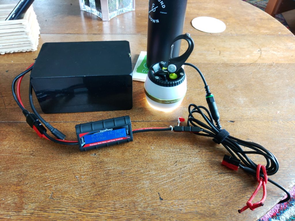
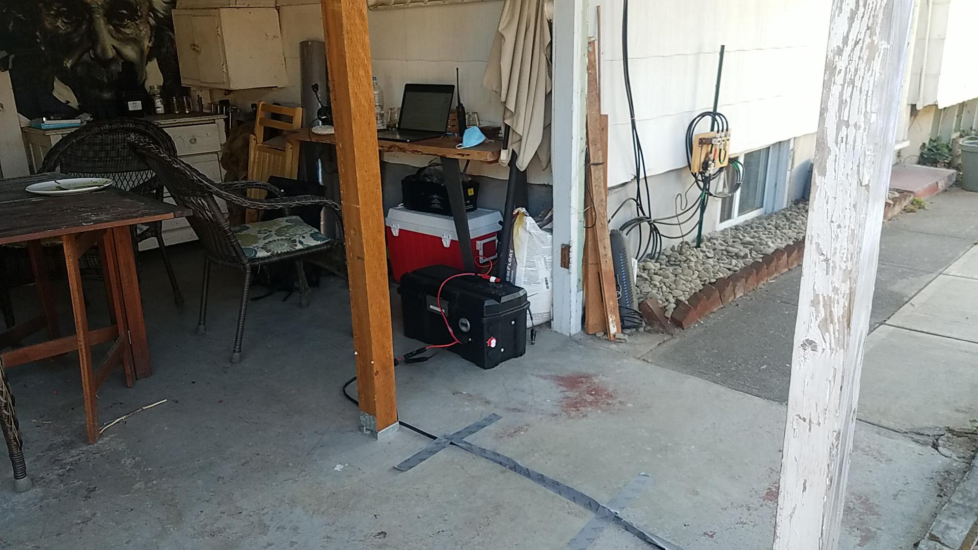
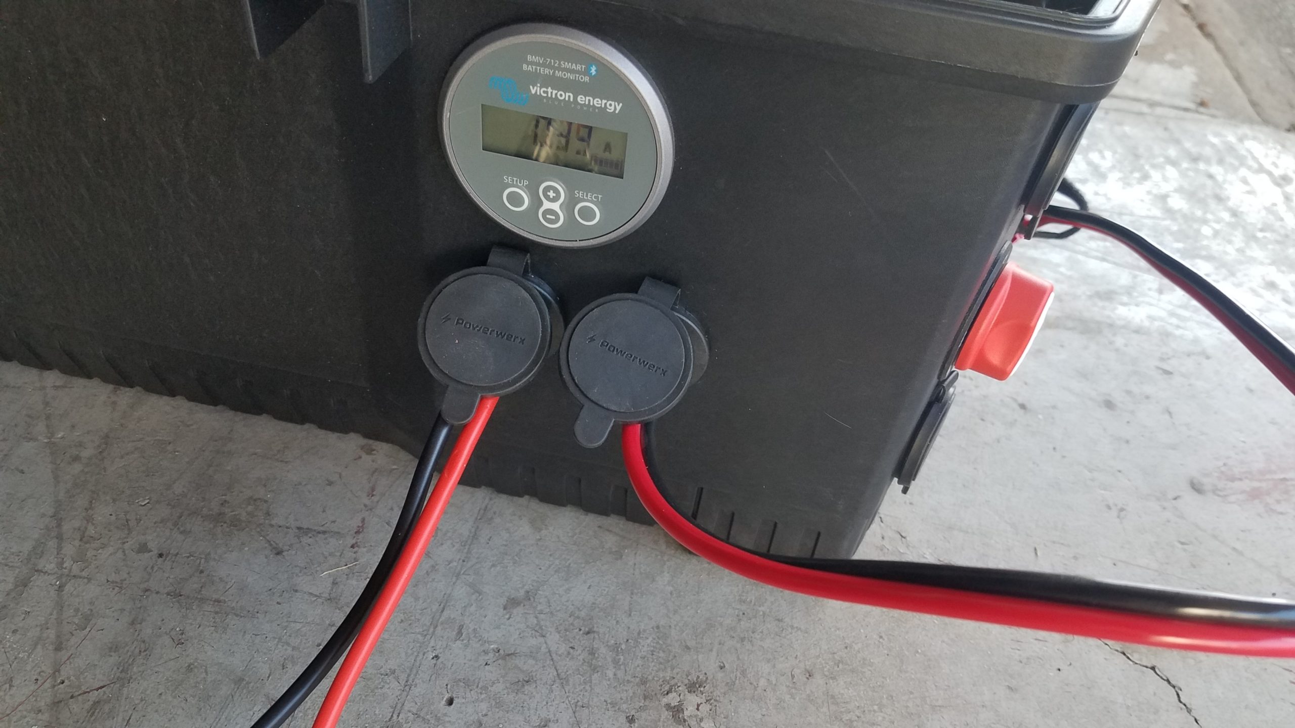
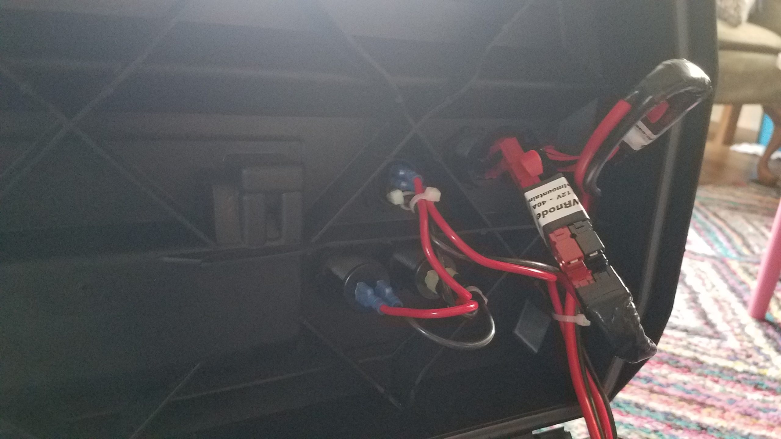
In this example I demonstrate testing a lighting device that runs on 12V and explain my methodology for hooking everything up and how I use back-of-the-napkin math to estimate power usage and requirements. In the above photo we have all three of our components for this specific test – a power source which is a battery in this case, the Powerwerx inline DC power meter, and load which is an LED lamp whose power usage I want to characterize. The Powerwerx inline meter supports a lot of measurements but in this post I’m going to mostly focus on current drawn and Ah, or amps per hour.

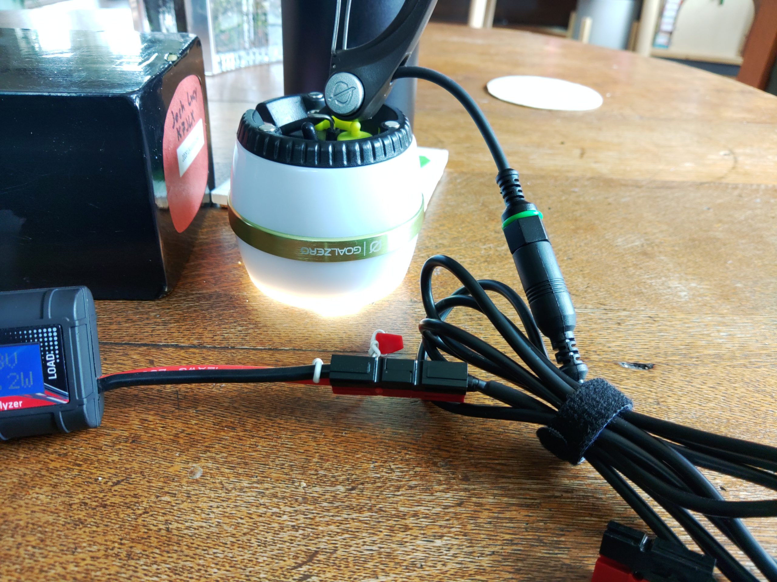
I started by connecting the power source to the “source” side of the power meter and then connected the load I wanted to test to the “load” side of the power meter. The images above show the light on but I will usually measure power with all the loads turned off to see if they draw current in the “off” position. It’s pretty common for devices to take a small amount of power even while off. This is called a parasitic load. The specific LED lamps I wanted to test have three settings: off, low, and high. I tested off and my power meter registered no current consumption. That’s probably because these lights have a hard off switch.

Power consumption with the switch in the “low” position

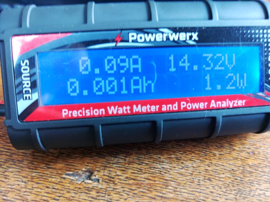
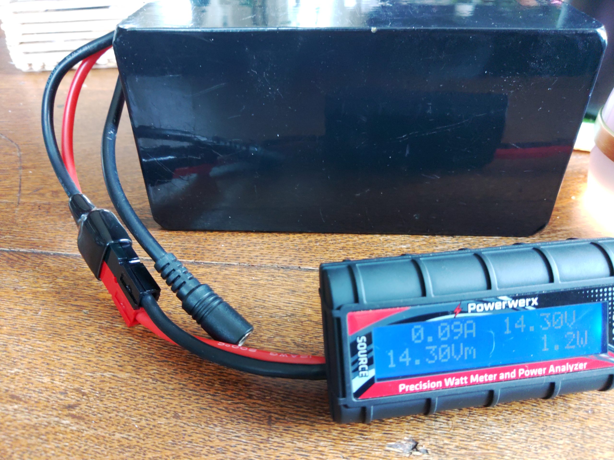
As you can see here this light draws 0.09A in the “low” position. If we were to run this device for 1 hour it would take 0.09Ah (amps per hour). You might have also noticed that there’s a measurement reading 0.001Ah. For this specific meter that means we’ve used 0.001Ah since the meter was connected to a load. There will be more on this measurement later.

The LED lamp with the switch in the “high” position

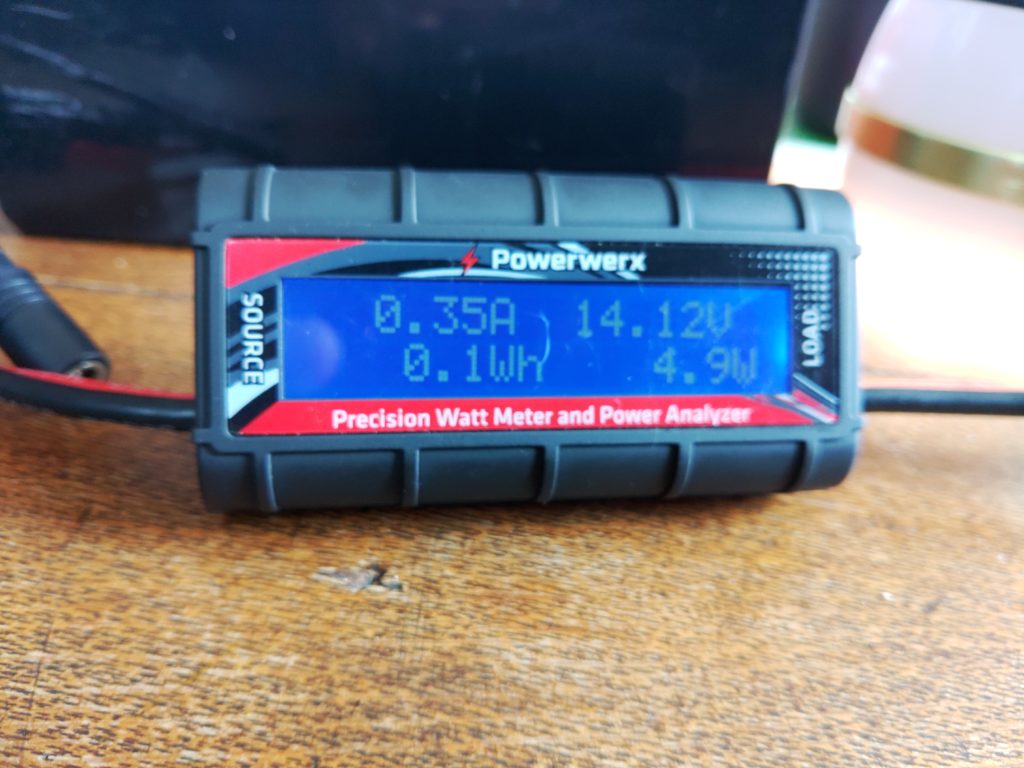
With the LED lamp in the “high” position it’s drawing 0.35A of power. With the information gathered so far I can estimate how much power I’ll need if I want to run this light for a certain amount of time, and I can figure out how much power I can expect it to take while it’s running. If we use the Ah reading I mentioned earlier we can also understand how much battery capacity we’ve used since the last time the meter was restarted. Let’s start with that since I mentioned it.

To determine how much battery we’ve used as a percentage I’d use the following formulas:

battery capacity used as percentage = battery capacity / battery consumed

battery remaining as percentage = 100% – battery capacity used percentage

For a theoretical battery with 20AH of a capacity and 2Ah consumed the formula looks like:

20AH / 2Ah = 10% capacity used

100% – 10%= 90% capacity remaining

Now let’s add time to the mix. I’m going to use a Yaesu FTM-100D radio as an example of thinking about how much power it will use based on the specifications from the manual. According to its specifications when it’s receiving only it’ll draw 0.5A. The max power it will draw when transmitting 50W on 2m is 11A. Using this information let’s figure out how much battery we’d need to operate this radio some percentage of the time for 8 hours. For the purposes of this post we’ll call the amount of time we’re transmitting our duty cycle. We’ll assume we’ll be transmitting at 50W for 10% of the time that the radio is powered on. The formula will look like this:

Ah used = current * hours * duty cycle

While the radio is receiving only during an 8 hour operating period we’ll use 3.6Ah of battery capacity:

0.5A * 8h * .90 (90% receiving time) = 3.6 Ah capacity used

Now we should compute power usage when transmitting at 50W:

11A * 8h * .10 (10% transmitting time) = 8.8 Ah capacity used

Total power consumption over 8 hours for the radio:

3.6Ah (RX only) + 8.8Ah (TX at 50W) = 12.4Ah

When we add them up we need at least 12.4 AH of battery capacity to run that radio for 8 hours while transmitting 10% of the time. If you want to run the radio for 16 hours transmitting 10% of the time you’d either need to be able to re-charge that battery to replace the discharged power before the battery gets too low or have a battery large enough to run the radio for 16 hours, meaning you had at least 24.8 AH of battery capacity. There’s also a way to cheat on battery capacity. If you can reliably charge your battery as you run your radio from a source like a solar panel you can replace current that’s drawn down by your loads. In that case you’d just subtract the current you’re able to supply from your charging source from the load. If you end up with 0 or a negative amount of current draw you’re able to power your radio without discharging the battery.

Figuring out how much power you use as you go

This section can apply to both bench testing and operating in “the wild”. This details how you’d use any power meter that’s capable of measuring cumulative power use while you’re running loads. The Powerwerx meter I mentioned earlier and the BuddiPole PowerMini have this capability. If you connect one of these power meters inline with your setup as you operate and run loads it will add the cumulative power drawn. This can be useful when you want to understand how much power you’ve drawn down on a battery. As I write this before the 4/3/2022 Portland Neighborhood Emergency Team chat net and NET net I plan to operate on battery with lighting during the net and record my power usage here later, but the thing I do is the following for both bench testing and off grid measurements:

  • Connect my power meter between the power source and load as described above
  • Perform whatever activities I would normally perform
  • When done I check the consumed Ah on the meter to get my battery capacity used
  • Calculate battery percentage used

Formula for calculating battery capacity used:

battery capacity used / battery capacity = percentage capacity used

For an example with a 20AH battery and 15Ah of capacity used during some activity I would have 25% capacity remaining on the battery. I can use this formula in the lab to estimate how much power I’ll need in the field later, or understand how close I am to drawing my battery down in the field:

15Ah / 20AH = 75% used battery capacity

100% – 75% = 25% remaining battery capacity

Adding it all up

When you perform this kind of analysis on devices you expect to run off of battery in the field you can begin adding up all your field components and understanding what your power requirements will be. If you know your lighting will take 2Ah to run for a few hours at night and 12 hours of radio operation might cost 13.2Ah you can say your station will take 15.2Ah to operate for 12 hours. As you add more devices such as phone chargers, laptops, etc. your power requirements will change. You can also use this methodology to reduce power consumption. For example if running your radio at 5W is sufficient to achieve your communication goals you could save a lot of power, requiring a smaller battery, or less recharging capacity. You could also achieve similar results by having fewer devices or keeping your radio transmissions more brief (decreasing your duty cycle). Comparing the sums of power consumption between different setups can also help you inform either your expectations of how to operate or what is possible with the setup you have. It can also help you right-size a battery or recharging system for your specific uses.

A real-world example

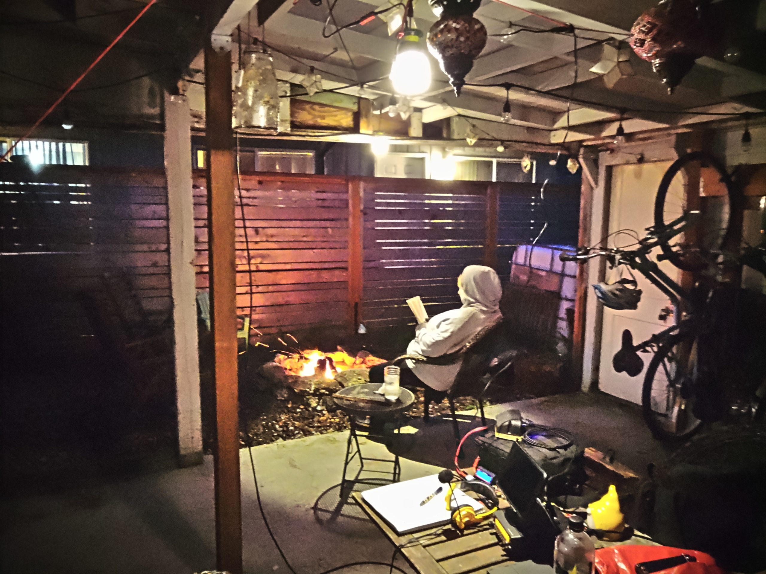
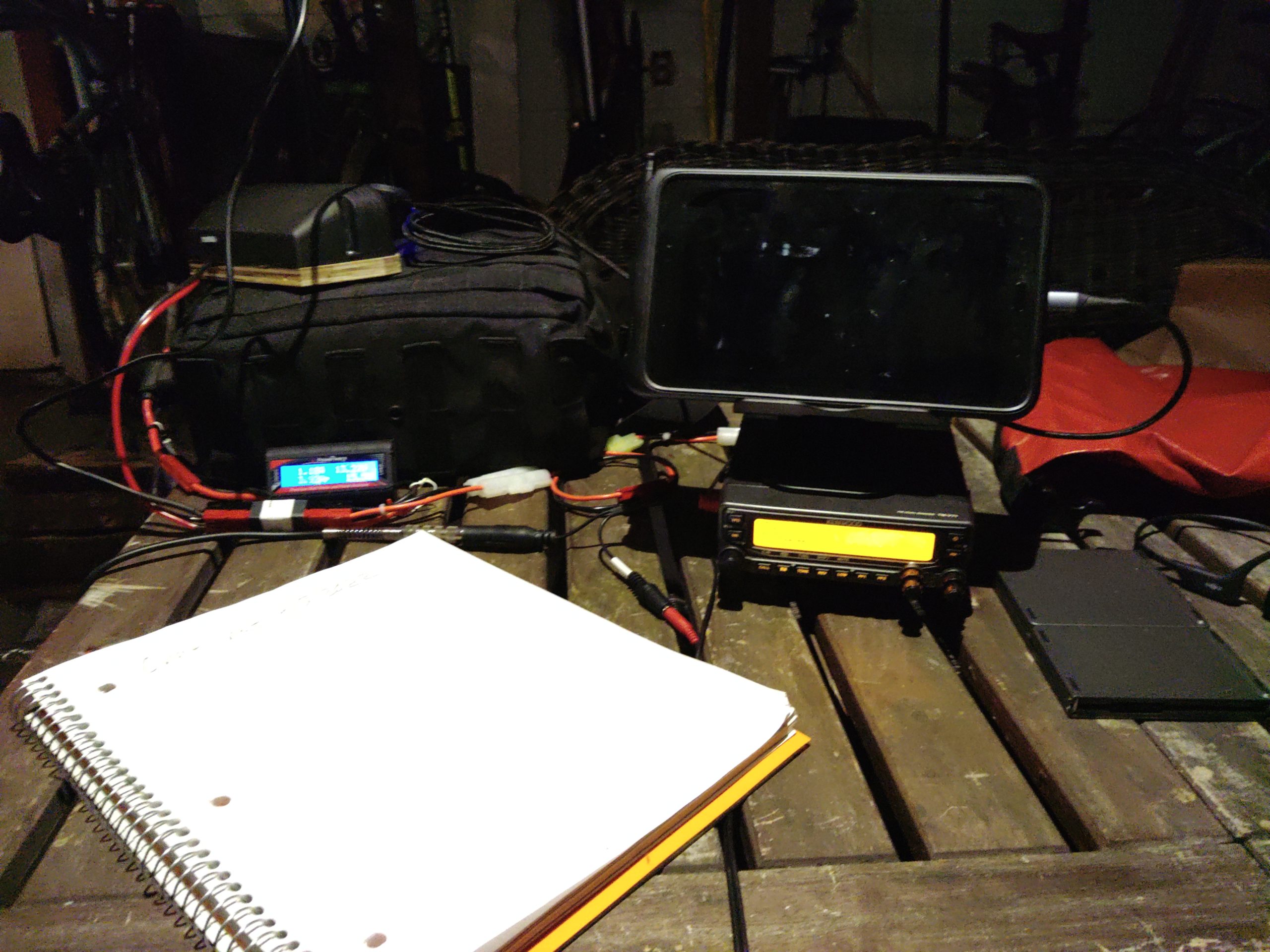
I wanted to add an update with another example of operating the radio in reasonable conditions doing a specific task that isn’t entirely theoretical, or just on-the-bench testing. Tonight I was net control for the Portland Neighborhood Emergency Team chat net, and I also participated in the Portland NET net as well. For most of the nets I was running two LED lights and I topped the last 25% of my tablet’s power off. I ran my Kenwood TM-V71A at 5w which drew about 3A when transmitting and 0.55A receiving. Both of the LED lights were set on low and consumed 0.1A apiece. The charger’s power usage varied depending on the part of the charging cycle the tablet was in, but at the end of 3 hours of running the radio, and about 2 hours of running both lights I used a total of 3.42AH of battery capacity. The battery I was using has a rated capacity of 40AH, so I used about 8.6% of its capacity (3.42AH used / 40AH of battery capacity = 0.086) doing both nets and listening on the first net’s frequency for an hour before it began. The first net that I was transmitting more on used the majority of the capacity, about 2.3AH. During the second net I only used about 1.1AH because I spent the vast majority of it listening as we ran lights and the tablet charger.

Tying it all together

By the end of this blog post I hope you came away with a good understanding of how I approach understanding and estimating my power usage and right-sizing my equipment for specific uses. This approach also helps inform how I operate when I don’t expect to have reliable power or when my situation changes and I’m not able to recharge batteries, etc. It can also show you how big of a difference it can make when you transmit less or when you add or drop devices from your setup.

This pattern can potentially be applied to other equipment like medical devices that can be run on battery. I’ve used the same method to profile my partner’s CPAP machine’s power consumption with various settings. I’ve been able to determine what sort of battery and charging system that will be required to keep it running when grid power fails or is unavailable (hint: turning off the humidifier and tube heater really saves a lot of power).

Notes after the fact

On the advice of Kevin, N6KVN I’m going to add a note about batteries. While this bit of the post is a bit out of scope it’s important to touch of the strengths and limitations of various battery technologies. Some batteries can be damaged by discharging them to 50% and others can be discharged to 20% or possibly lower before damage occurs. It’s important to understand the characteristics of the equipment you’re running. If you’ve read other posts of mine you’ll notice that I field a lot of LiFePO4 batteries. One of the reasons (apart from weight and other safety factors) that I tend to use them is because they can be discharged to a depth of 20% of remaining capacity before they’re permanently damaged. Most common lead-acid battery tech (think car batteries) can only be discharged to 50% before permanent damage to the cells occurs, but they are much cheaper than lithium batteries. Comparisons of various battery types is an entire post of its own, but these things are worth mentioning as you size your system and plan for the amount of energy you expect to discharge or plan to use. As an example my 100AH battery really has a usable capacity of 80AH because if I were to discharge the battery to 20%, or 20AH it would cause permanent damage to the battery (100AH capacity * 20% limit = 20AH, 100AH capacity – 20AH limit = 80AH of discharge before damage). This information should be listed by the battery manufacturer. If it’s not included I’d recommend reaching out to their support team.

Bench testing 100Ah battery box improvements

Battery box sitting on a concret slab with wires running from it.
Battery box with solar power and a 90W USB charger connected via a PWRNode
Zoomed out view of the battery box with a wire running to it from the right that's taped down, a laptop on a bench near the battery box with wires running into it from the battery box.
A wider view of the work area with the solar cable taped to the ground and the laptop on a workbench

With a potential COVID-19 exposure I decided to work outside in order keep my housemates’ exposure as low as possible. This afforded me the perfect opportunity to test running a high performance laptop from my batery bank and on solar power. I wanted to bench test integrating a West Mountain Radio Epic PWRGate into the existing battery box that had been intentionally designed without and integrated charger. The first and second days of the test with good and poor sunlight respectively went well. The solar panels were holding the battery up and by the time I was done working the battery was fully charged. It is worth noting that earlier in the morning the laptop was running on the battery, but as the sun came up the battery began recharging in both cases. Of course the battery charged more slowly and sometimes went into a discharging state on the cloudy day but ultiately all the power drawn from the battery was replentished.

Two powerpole ports populated with power cables on the power box's side.
The added solar (left) and UPS (right) powerpole connectors
View of closed powerpole ports, two populated powerpole ports, and a red disconnect switch as seen from the corner of the battery box.
The existing 30A charging port (top), added disconnect swtich for the charger (middle), and added DC in port (bottom)

I added three new Powerpole ports to support the installation of a West Mountain Radio Epic PWRGate for use as a multisource battery charger and to allow one port on the battery box to function as a UPS, one as a DC charging input from a vehicle or other 12v power supply, and a solar panel input that can work with lower voltage (<30V) solar panels. I also added a charger disconnect switch that prevents the charger from acting as a parasitic load when it’s not in use. The specific disconnect switch I added allows the red rotary part of the swtich to be removed n the event you want to make sure the charger isn’t connected to the battery by mistake.

Open battery box revealing connections between internal components including the Epic PWRGate.
Opened battery box with the Epic PWRGate connected for testing

The Epic PWRGate connects to the ports with 10GA stranded copper wire to support 30 amp loads. The “battery” port on the PWRGate is connected to the battery via the DC disconnect switch and the DC subpanel. The leg of the circuit that connects the battery to the charger is also fused with a 30A fuse to allow it to operate a full power radio via the UPS port. The Epic PWRGate will charge a battery with a max current of 10A. I also added an optional temperature probe connected to the positive battery lug that will cut the charger off when the battery gets too cold or warm to prevent harm to the battery. The temperature parameters are configurable using the USB port. The appropriate USB cable, USB C, and USB A OTG cable adapters are included to connect a device with a serial terminal emulator installed.

Block diagram of 100Ah battery box

This updated simplified build diagram for the 100Ah battery box includes the modifications that were being bench tested and will likely remain as a permanent addition to the system for charging from a vehicle or charging from a lower voltage (<30v) portable solar panel.

As a side note an added advantage of including a charger like the Epic PWRGate to this setup is that it can be re-configured to charge another battery, even of a different chemistry from the 100Ah LiFePO4 battery. You can charge a smaller battery or even charge a lead acid battery from it as well. This will require changing jumpers if you’re not programming the unit with a USB port, but I prefer programming it with a USB port as I get a better degree of control over the settings such as charge current than the onboard jumpers provide. It will also require swapping the battery and DC ports. The battery should be connected to the DC port and the DC port should be connected to the battery being charged. In the event the charger is re-configured I also include the custom LiFePO4 battery settings for my Relion RB100 that the kit is designed around so they can be restored on the charger without requiring memorization.

Solar panel suspended from paracord in the sun.
Suspended foldable solar panel

I also ended up having shading issues in the space that was available to set up the solar panels so I used the built-in eyelets and some paracord to suspend the panel in the sun to avoid shading on the ground. I was also able to slide the panel laterally on one piece of cord running left to right (east to west) near the water tank pictured. The other piece of paracord goes through both of the eyelets and forms a tiangle whose point is a knot and the single line of paracord runs back to a single anchor point from the triangle, and is pointed south. You can slide the panel side to side on the paracord running right to left (east to west) as the sun’s position in the sky changes. Getting the panel off the ground was extremely helpful because it got the system out of shadows cast accross the ground most of the day, and also required less maintenance as shadows tracked across the ground and threatened to partially or fully shade the solar panels. Instead the shadows were cast under the suspended panel.

The 100W folding panel was able to charge both a 19″ Macbook Pro connected to a 90W USB C car charger and a phone the an entire work day. This worked well on a bright day and on a cloudy day using this new configuration. I leverage MC4 connectors for the 100W panel to harden the connections against rain and dust. They’re adapted to Anderson Powerpole connectors for connection to the battery box using a pigtail I store in a zippered pouch on the back of the folding panel along with rolled lengths of wire with MC4 connectors attached.

This is an update to this post about building the battery box.

100Ah battery box build

Ok, so this is a big one. I wanted to build a battery box that could keep me going a few days without being able to charge while camping and/or operating. I also wanted accurate power accounting and the ability to understand my power consumption and have alarms when usage exceeds specified thresholds, providing the opportunity to either adjust usage or in an emergency not be surprised when I drop out. I also wanted to design the system for maximum flexibility when it comes to charging and connecting loads. Most commercially-available systems that met capacity and power needs were designed around inverters and larger 30+ volt solar panels that were designed to mount on structures or large vehicles like RVs or vans rather than the smaller and more portable 18v open circuit foldable panels that are used more commonly for my purposes. Having a wider range of panels that I can use is better because it would be good to charge from either so not building in charging was ideal. I also found the options for high-amperage DC connectors lacking in many pre-built options. Some units would have one or two 25A outputs, but those are at the max current range some of my radios will draw at full power. I wanted some breathing room current-wise. In the event I wanted to operate one of my bigger radios at full power I’d rather not risk burning a fuse out or damaging my power source – especially in the field while I’m relying on it. It’s also nice to have many connectors available on the source which eliminates the need for a bunch of splitters. None of the commercially-available options I evaluated provided more than two high amperage connectors. Finally, I wanted a couple USB fast chargers for my and my partner’s devices which many commercial options provided, but they’d typically provide a single fast charging port.

I took some inspiration from a Powerwerx box that a fellow ham and NET team member Laura, KI7ZZQ purchased. That battery box was designed to accommodate a 50-70Ah battery which wouldn’t physically fit any of the 100Ah batteries I had been considering during the design phase, but it provided me a rough template I could build from in terms of layout. As with that box just including power distribution and monitoring in the box was a way I could reuse existing systems I have that perform well without having to buy more of those components. Buying a bunch of new parts is pretty expensive so not including more core devices in the box is definitely a plus.

This was not a cheap project, but I think it’ll be worth it.

Theory and design

By selecting a 100Ah battery I get 80Ah of usable power from the system without significantly decreasing the battery’s lifecycle. Using LiFePO4 batteries instead of lead-acid means I get an additional 30% depth of discharge without the destructive effects of discharging to 50%… The LiFePO4 battery I selected also weighs 26lbs. A similar capacity lead acid battery would weigh a lot more and probably require a much sturdier and expensive enclosure. Another advantage of LiFePO4 batteries is the lack of battery memory – that is to say the useful lifetime of a battery isn’t diminished by leaving it in a partially-charged state. Some battery technologies suffer from that problem which is a problem if you’re in a situation where you might not be able to completely recharge the battery completely during use. As far as parts go I wanted to attempt to source the parts I didn’t already have from a variety of vendors… I had a preference for smaller and more local vendors, but that didn’t work out 100% of the time. The enclosure (tool box) and a 1 1/8″ hole saw are two examples of where that didn’t work. The bill of materials will list the source of each component.

So let’s start with the system design itself. There are a few core components that I knew I’d probably want from designing a bigger high amperage system when my partner were considering purchasing and building out a van for camping/touring. The core parts that everything else would be designed around are:

  • 100Ah LiFePO4 battery
  • Reliable battery state and power usage monitoring capability
  • Battery disconnect for safety and preventing parasitic loads from draining the battery
  • Circuit breaker for the battery to prevent damage to components or fires
  • DC subpanel to split out and protect branch circuits
  • Two switched USB rapid chargers.
  • Flexible charging – AC-to-DC chargers (wall socket, generator), solar panels of various types, and DC-to-DC (vehicle, independent DC power supply, DC generator outputs)

Those components are roughly connected and arranged as follows. Chargers can be connected to any of the powerpole connectors listed below, and so can loads. The only loads that wouldn’t be connected to powerpole connectors are devices directly connected to the built-in USB A/C rapid chargers. You’ll notice there’s a power line running from the battery to the 500A shunt resistor and power supply that feeds the Victron BMV-712 through a 100mA fuse, bypassing the circuit breaker which also doubles as a battery disconnect. That’s intentional as the BMV-712 requires constant power to track battery state and if powered off it will lose its zero-point configuration. This is the only parasitic load that isn’t switched in this system apart from the BMS built into the battery, but it’s required to get accurate battery status so I compromised.

Block diagram showing electrical connections between a battery, shunt resistor, circuit breaker, DC subpanel, USB chargers, and power connectors.

Materials / parts

High amperage and distribution components
DescriptionQtyMake and modelVendorLinkNotesTool?
100Ah LiFePO4 battery1Relion RB100LightHarvest SolarHereN
Red #2/0 welding cable, 10′1?HereN
Black #2/0 welding cable, 10′1?N
100 amp circuit breaker *****1Eaton 285100FHereN
6-position 100A DC subpanel1BlueSea 5025HereN
Hammer-type crimping tool1TE(?)HereY
Battery monitor1Victron Energy BMV-712HereN
#2/0 Lug Ring Terminal (5/16″) *3?HereN
#2/0 Lug Ring Terminal (3/8″) *3?N
#2/0 Lug Ring Terminal (1/4″) *5?N
10A LiFePO4 14.6v battery charger1Bioenno Power BPC-1510ABioenno PowerHereDedicated AC-to-DC chargerN
Tool box1Dewalt DWST24082 One Touch Tool Box, BlackHome DepotHereUsed as enclosureN
#10-24 3/4″ cap screws and nuts (x8?)1?HereN
#10-24 1″ cap screws and nuts (x6?)1?HereN
#10-24 Bonded neoprene washer (x4)3?HereN
1 1/8″ hole saw1?HereUsed for Powerwerx panel mount devicesY
Panel mount powerpole socket (x2)2Powerwerx PanelPole2PowerwerxHereN
Panel mount powerpole socket (x1)1Powerwerx PanelPole1HereN
USB A QC + USB C PD charger, panel mount2Powerwerx PanelQCUSBCHereN
Bonded 10GA stranded copper wire, 25′1Powerwerx Wire-RB-10-25HereUsed for 30A branch circuitsN
Bonded 14GA stranded copper wire, 25′1Powerwerx Wire-RB-14-25Used for 15A branch circuitN
Powerpole to “cigarette lighter” adapter1Powerwerx SOC-PPHereStored in the enclosure as an adapterN
4-Way powerpole splitter2West Mountain Radio PWRNodeHam Radio OutletHereUsed as splitters for the 2x panel mount powerpole socketsN
Panel mount rocker switch w/red LED, 15A max1Powerwerx PanelSW-RedHereN
15/30/45A red powerpole housings6Powerwerx PowerpoleCaseHereN
15/30/45A black powerpole housings6N
Powerpole retention clips6N
45A powerpole contacts22N
Powerpole crimper1Powerwerx TRICrimpHereY
F2 blade connectors, 12-10GA3???N
F2 blade connectors, 16-14GA4???N
Lug ring terminal, 12-10GA6???N
Lug ring terminal, 16-14GA2???N
7.5A ATC blade fuse *3???N
30A ATC blade fuse *5???N
Assorted ATC blade fuses6???Included in enclosureN
Packing foam **????N
Electrical tape ***1???N
1 1/4″ bolt and flange nut ****1???N
Zip ties5???N
3/16″ (?) drill bit 1???Used to drill holes in plastic fins in toolbox for zip tiesN
Electric drill1???Used w/hole saws and drill bitsY
2″ hole saw1???Used to drill a hole for the Victron BMV-712 panelY
Phillips screw driver1???Y
Metal shears1???Used to cut #2/0 welding cableY
Diagonal cutters1???Y
Socket wrench1???Y
?mm socket1???Used for shunt boltsY
?mm socket1???Used for battery terminal boltsY
?mm socket1???Used for #10 nutsY
?mm socket1???Used for DC subpanel 100A contacts
Needle nose pliers1???Used to help pull wires, tighten panel mount nutsY
Claw hammer1???Used w/ the TE hammer-type crimping toolY
Pocket knife ******1???Y

Legend
? Can’t remember/unknown
— Same as above
* Includes spare(s) or extra(s)
** This is small-cell plastic foam used as packing to keep the battery from moving around a lot
*** Used mostly to bind wires and as extra insulation on the #2/0 ring terminals. Also used to physically shore connections up due to gaps in wire jacketing or potential stress points from bends.
**** Used as insurance to hold the toolbox closed in case the latch is opened unintentionally
***** Doubles as a battery disconnect switch
****** Used to clean plastic burrs left from the hole saws and to cut the jacketing on the #2/0 cable in preparation for crimping

Assembly

This was done in a a couple phases – in part because I was waiting for things to come in the mail, and in part because I sort of “winged it” building this out in terms of mounting components to the enclosure. The first thing I did was pick locations for each of the high amperage components: the battery, BMV-712’s 500A shunt, 100A circuit breaker, and the DC subpanel. I made sure to allow for enough space to run cables to and from each component before drilling holes for them. The battery was pushed to the left side of the tool box. This makes it a bit awkward to carry but creates enough space in the right side to mount everything.

Once I found a good placement for the components that required mounting I just drilled holes in the enclosure using the components as a template. For each component I drilled an initial hole and inserted one of the #10-24 cap screws in the hole to hold it. I then drilled out a second mount and placed another bolt in it. After I’d placed all the components and got the holes drilled for them I added the #10 bonded washers with the neoprene side on the outside of the enclosure. To minimize jagged edges from threads on the outside of the enclosure I put the phillips end of the cap screws on the outside as well. The nuts and lock washers were placed on the inside.

The next step was to route, measure, and cut the high amperage #2/0 welding cable between each component. I did a dry run of the cable from component to component and cut each piece to length. I ran a piece of from the negative battery post bolt to the BMV-712 shunt battery terminal, cut it, ran another piece from the shunt to the negative terminal of the DC subpanel to the BMV-712 shunt load terminal, and cut it. I then took the red #2/0 welding cable and ran it from the positive terminal on the DC subpanel to the 100A circuit breaker, cut it, and then ran another piece from the circuit breaker to the positive battery terminal, and then cut it.

For each piece of #2/0 welding cable I cut I stripped enough jacketing off of the end to fix the appropriate #2/0 lug ring terminal to the wire. Make sure the hole on each lug ring terminal matches the post you’re planning to connect it to. It’s worth double-checking before you crimp since each section of wire is cut to length. After verifying that I was using the right ring terminal for each connection I crimped them to the #2/0 welding cable. I then wrapped the bare metal parts of the lugs that might be prone to shorting with electrical tape since I didn’t have any heat shrink tubing. I also used the tape to shore the joint between the jacketing of the welding cable and crimp-on connector.

The next step is to hook the high amperage wire up to each component. This will help us figure out where to run the legs from the DC subpanel and to help us properly place the panel mount components without interfering with the high amperage wire runs and components mounted inside the enclosure. Before making the connections between components verify the polarity of the connections and break the circuit by pressing the reset button on the circuit breaker. The connections should be made according the the simplified wiring diagram above.

Completed mounting of all components in the lower portion of the enclosure

The next step is to place and mark each panel mount component. I chose to mount the BMV-712’s meter on the front of the tool box to the right of the latch since I mounted the DC subpanel on the flat part of right end of the toolbox. I mounted the 1x powerpole panel mount component on one of the angled surfaces on the right end of the enclosure so I could connect a charger easily when it’s stored on a shelf. I picked spots for the panel mount components on the lid because I think that’s going to be the easiest spot to make connections in the field. All the panel mount components were placed in such a way that the panel mount nuts cleared the plastic “fins” on the inside of the enclosure. Special care should be taken when placing components in the lid. There are a lot of plastic fins on the inside of the lid. Use the 2″ hole saw to cut the hole for the Victron BMV-712’s meter, and for all the other Powerwerx panel mount components use the 1 1/8″ hole saw. You might need to shave the decorative raised lines on the lid down with a pocket knife to ensure that the panel mount components mate to the outside of the lid properly.

Photo showing placement of all panel mount components

At this point it’s time to start making the connections from the subpanel to the panel mount powerpole connectors. Since I used 10GA wire capable of handling 30A it’s hard to daisy chain between ports so I opted to use some PWRNode splitters to make the connections to the 2x panel mount powerpole sockets. I made some shorter 2″ stubs of 10GA wire and crimped 45A powerpole conductors on both ends of each stub. Connecting all 4 ports requires 8 2″ stubs. Once I crimped the 45A conductors on I added the powerpole housings to one side of each stub. The other side of the stub was inserted into the panel mount connector. Each panel mount socket is connected to a single run of cable from the DC subpanel with powerpole connectors on the end of it. The idea is that each socket can support up to 30A of total current draw. Once that was complete the side with the housings were connected to the PWRNodes and powerpole retention clips were installed to keep all the powerpole connectors in place. The 1x powerpole connector was run directly to the DC subpanel. Each leg was then fused in the DC subpanel with a 30A fuse. I used some electrical tape to support the “joints” between the powerpole connectors that lead to the DC subpanel and the powerpole connectors themselves.

The next step in wiring the system is to connect the panel mount chargers in parallel and switch them with the rocker switch using the 14GA wire. This is accomplished using the connections as detailed in the simplified electrical diagram. The brass connector on the switch connects to the ground, the middle connector connects to the DC subpanel, and the silver connection on the end connects to the USB chargers wired in parallel. The photo below details how the connections to the panel mounted devices and sockets. I drilled a hole in one of the fins on the lid of the toolbox and wire tied the wires coming from the DC subpanel to the lid to keep the wires from migrating a lot during transport. I also used wire ties to hold some of the wires together coming out of the individual parts.

Now that all those connections are complete we can re-connect the battery, and while we’re at that we’ll hook the BMV-712 up. The BMV-712’s box has a handy connection diagram. In this step we’ll connect the battery and the BMV-712. First connect the BMV-712’s red (positive) wire connected to the temperature sensor lug to the battery using the ring terminal along with the terminal on the #2/0 welding cable. Both should connect directly to the positive battery terminal. Take care not to short the pin end of the BMV-712’s red power cable while connecting it. Once that’s connected to the positive battery terminal connect it to the B1 pin on the BMV-712’s shunt, and connect the black temperature monitor cable to B2 on the BMV-712’s shunt. The BMV-712’s manual will detail how that connection should be made. Now connect the gray 6-pin modular data cable from the shunt to the BMV-712’s panel mount meter. Once that’s been hooked up you can connect the negative battery terminal to the black wire leading to the battery side of the BMV-712 shunt. When properly connected the panel should light up blue and the display should become active. [Note: this was updated to include directions to connect a BMV-712 temperature sensor.]

Once all these connections are made and the battery is re-installed make sure you install a 7.5A fuse in the subpanel on the leg that connects to the USB chargers. If the 7.5A fuse blows during testing one or both of the USB chargers are wired backward. Use the + and – on the bottom to properly wire the positive and negative sides of the charger. Install 30A fuses on each leg that leads to powerpole panel mount sockets.

Now we’ll pull the yellow reset bar on the breaker back in to energize the DC subpanel. Once the subpanel is energized we can test the USB charger leg of the circuit by activating the toggle switch. The red LED should activate on the toggle switch, and both USB chargers should show their voltage with blue numerical LED displays. If all three of those work that’s wired correctly.

As a bonus I added some scraps of plastic closed cell packing “foam” around the battery to dampen vibration and shock to help hold the battery in place.

The installation is complete we can move onto programming the Victron BMV-712.

Configuring the Victron BMV-712

At this point we should set up the battery monitor. Some of the instructions in this section come in part from instructions provided to me by LightHarvest Solar. I modified some of the values in the configuration to better fit my use-case. The instructions in this section assume you’ve charged the battery completely using an appropriate LiFePO4 battery charger. I used the Bioenno charger listed in the bill of materials to fully charge the battery before configuring the BMV-712. To begin you’ll want to install the VictronConnect app on a device that it supports which also has Bluetooth. There are versions for IOS and Android.

After opening the app you’ll want to select your BMV-712 and pair with it. I also recommend changing the BMV-712’s pin to make sure someone doesn’t pair with it and modify its settings, especially if you’re around RVs or others with a Victron battery monitor. You can then modify the settings on the device. The major configuration tasks to do are configuring the parameters for your battery and doing a zero-point reset once your battery has been fully charged. To begin with we’ll configure the battery monitor with the properties of the Relion RB100. You can leave all the settings as defaults unless they’re specified below. I got the initial values and instructions to configure the battery monitor from LightHarvest Solar. It was provided with the purchase of the BMV-712. After opening settings and choosing “Battery” set the following:

  • Battery capacity: 100Ah (this is a 100Ah battery)
  • Charged voltage: 13.9V
  • Discharge floor: 20% (This is the lowest capacity you want the battery at)
  • Peukert exponent: 1.00
  • Charge efficiency factor: 99%
  • Current threshold: 0.10A
  • Time-to-go averaging period

Optionally, you can configure alarms for the system. I turned on the alarm buzzer and set the “Low SOC alarm” to go off at 40% and clear at 45%. Since you don’t want to draw the battery down lower than 20% I picked 40% to give me a warning well before I draw it down. If you draw the battery down below the discharge floor it can be damaged. You can also optionally configure a temperature alarm if you have the BMV-712 battery temperature sensor. See the “updates” section at the bottom of this post for details.

Once the battery has been configured and ALL loads and chargers except the BMV-712 have been disconnected you can then click the “synchronize” button, and then click “calibration”. Synchronize sets the battery state-of-charge to 100%. Calibration zeroes out the current measurement on the shunt resistor. If you disconnect the battery monitor you’ll need to redo this part of the process starting with a full charge.

Using the BMV-712

While this post is mostly focused on the app the display panel on the BMV-712 can display the status information using the arrow keys on the front panel. Navigating that is pretty easy, but I’d also recommend reading the manual as there’s more to the panel than just displaying data. The most common screens I use in the app are the device list which is used to manage Victron devices. They have an entire ecosystem of devices that can be managed and monitored from this app. I go through this to connect to my battery box. The battery box has been renamed in the settings (gear icon seen in the other screens). The status page shows you all the current stats for your battery – state of charge, voltage levels, current, and power. There’s one thing that’s cut off at the bottom which is the status of the control panel’s relays. For my configuration the relay is open since it’s not really doing anything. The history tab shows you stats for your battery over time. This data can be cleared, but it’s nice to understand what you’ve done with your battery over time so I probably won’t be clearing that until I replace the battery in the system. The trends tab is really nice to use when you’re watching your battery in real time from within the app. You don’t get data points when your app isn’t connected unless you get a Victron Cerbro GX or similar device but that’s overkill for my use-case.

Problems left to solve

There are still some problems to solve. I need to install some sort of barrier that prevents the battery from moving to the right inside the enclosure. I’m thinking about bolting a barrier into the enclosure to prevent too much movement. The toggle switch on the top isn’t weather resistant either. The toggle switch comes with a plastic cover but it’s impossible to install without the rocker switch popping out of the panel mount.

Updates

I decided to add a temperature sensor to the BMV-712 in order to make sure I’d get an alarm if the battery was out of the appropriate range to charge which is a more narrow range than the discharging temperature. The changes I made to connect the battery temperature sensor was to purchase a temperature sensor for $25. I disconnected the old wire running from the positive battery terminal to the current shunt, connected the new one, and connected the new larger lug to the battery terminal. I then connected the black wire for the temperature sensor to the open input on the shunt. After that I configured the BMV-712 to use the second input as a temperature sensor using the web application. Then I configured my high temperature trip temp to 55C and the high temperature clear to 53C. The alarm will go off 5C before the battery’s charge limit of 60C. The low temperature alarm was set to -15C and the low temperature clear was set to -13C. -15C is 5C above the battery’s minimum charging temperature limit of -20C. The connection diagram has been updated to reflect the new temperature sensor connection. This post talks about recently implemented changes to the battery box.

Teaser: 100Ah LiFePO4 battery box

A new project is underway: a 100Ah battery box with a smart power monitor and some good safety features. It’s based around a Relion RB100 battery with a Victron BMV-712 smart battery monitor and is designed to keep my low voltage gear and radios running for multiple days and can be combined with my existing solar charging gear or a vehicle-based DC charger. A detailed post about the build including a bill of materials will be forthcoming once I complete the build!

Black DeWalt toolbox with a side-mounted power meter and black sealed connector port on the top.
Partially completed 100Ah battery box

Thinking about off grid / grid down networking and ham radio

Hello all, I wanted to talk a bit about the subject of off grid networking and digital ham radio communications that leverage modern technologies that we use and rely on every day. I’ve been doing a number of experiments that leverage Raspberry Pis, phones, tablets, and laptops in the shack, in the field, and while traveling to operate one or more ham radios.

I’ll go through the ways I’ve configured my field computers to operate in: as a single device, as two or more devices, as devices connected to a $25 travel router running OpenWrt, and as equipment connected to a home network. The reality of this setup is that all my off grid computers work in one of two ways given any situation, but with some subtle differences.

The broad scenario 1 is when one of my Pis detect a wireless network they’re configured to connect to. This can mean they’re connected to a familiar Internet-connected wifi network at the QTH or elsewhere as a client, OR they’ve connected as a client to a wifi network generated in the field by another device designed to operate off grid. This means the device is acting as a standard wifi client.

The second broad scenario that one of my Pis supports is that it does not detect a recognized wireless network and generates its own. Only one device should be in this mode in any scenario. Once a single device generates a network any additional Pis, laptops, tablets, phones, etc. should connect to this Pi which will also automatically serve DHCP, DNS, NTP (in some cases), etc. This host then becomes responsible for handling basic network services as well as its ham radio related functions. There is, however, a drawback to this scenario with my current setup. For some reason my Raspberry Pi 4s and Raspberry Pi Zero W will stop passing network traffic after a few minutes. The solution to this problem is just to re-connect to the wireless network and things work again, but reliability is an issue. If you can’t simply log in and reconnect a Pi you have to reboot it. I address my solution in one of the more specific scenarios discussed later.

By supporting these two broad ways of handling connectivity we can create effective on and off grid networks. This makes sense because the first host that gets powered up has the chance of becoming the master of the wireless network. By coordinating the name of your off grid or standalone wireless network and its pre-shared keys you can create a network that can be formed on the fly, and that can have at least some self-healing properties in the event of a device failure. If all the nodes are capable of becoming an access point with all necessary network services in the absence of another we can ensure our services are available, or are as available as possible.

Let’s start with the five very specific scenarios we mentioned earlier. Notice that these five scenarios are mostly combinations of the two very broad ways our devices are configured to behave.

First let’s say that things are normal and we’re doing some digital HF or UHF/VHF work in the shack. Our local infrastructure is working fine, our Internet connectivity is fast and working well. Because all of our devices are clients on our home network we can use any device to access VNC, SSH, HTTP, or Winlink services on our Pis without issue while watching our favorite streaming service. All the Pis we have powered up are clients to an established network.

Secondly let’s talk about a scenario where we’re on battery but no configured wireless networks are available. Maybe we’re in an emergency scenario, camping, or on the road. Our Pi attached to our radio generates a new wireless network that you can connect to and starts the necessary DNS, DHCP, or even NTP service to allow wireless clients to connect and use provided services. Maybe this Pi is running JS8Call/FlDigi or Pat Winlink. You just connect your phone, tablet, or laptop to this network and access the documentation web server, Winlink web page, or use VNC/SSH to control the Pi. We’re now able to communicate using our radio via digital modes and read any documentation we stored on the Pi. It should be pointed out that none of my field-portable Pis have keyboards, displays, or monitors of any kind when in normal use. I rely on other devices for those functions to cut down on power consumption and bulk.

Our third scenario assumes one operator with no configured wireless networks, but is running two radios. Maybe we have one Raspberry Pi attached to a UHF/VHF radio that’s set up for packet Winlink, and another HF rig running JS8Call. The Raspberry Pi that booted first is serving our wireless network and basic network infrastructure services that allow subsequent devices to connect. The operator is now able to connect to to the generated wireless network and use Pat Winlink as well as JS8Call or FLDigi. One person and one device can now manage two radios set up for different purposes! The trick is that we might not have 100% due to the connection issues with Pis when they’re in access point mode.

For our fourth scenario we’ll modify the last scenario a bit. We have one operator with one device connecting to two radios over the wifi connection. This time we’ll introduce our modified $25 wireless access point. It’s now generating the wireless network, serving DHCP, DNS, and NTP if one of our Pis with GPS units is connected. All Raspberry Pis are now in wifi client mode so we no longer have the connection reliability issues in our second and third scenarios! What’s even better is that if we have a wired Internet connection we can now plug that into the travel router and have full Internet connectivity for our Pis and operator’s device. Sweet!

Our fifth scenario builds on the fourth, but we’ll introduce one or more operators using one or more devices. This could also apply to the third scenario with a Pi hosting the wireless infrastructure without an access point but we’ll ignore that. Every radio operator connected to the wireless network can now queue up e-mail on Winlink or take turns using VNC to control our HF rig. All the operators on the network now have access to the documentation server because it’s just a web page that serves files. We now have a field network that can serve more than one radio operator, and we can be more efficient sending email over Winlink by batching, and we can also decide to create an APRS server that allows multiple instances of APRSDroid or some other KISS over TCP client to connect if we’d like.

I hope you came away from this thinking about different ways we can build resilient and flexible systems even when working off grid or in emergency situations. A minimal amount of additional hardware combined with some preparation ahead of time can allow us to use more efficient or sometimes required digital technologies off grid and can even allow a group of operators to save power by sharing radios and batching messages rather than dealing with the overhead of connection setup for modes like Winlink!