Starlink Mini as emergency comms platform

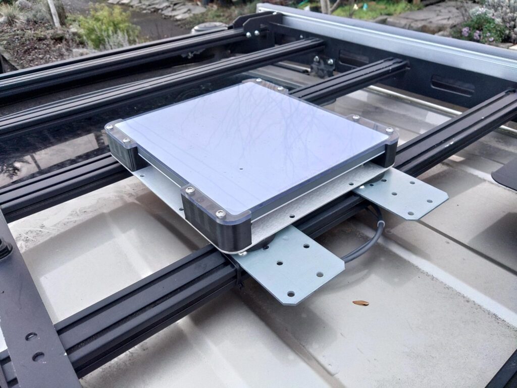
Welcome to another post. This one covers potential uses for the Starlink Mini in an emergency communications, gird down, or other scenario where Internet connectivity is required but unavailable using other means. There are a number of use-cases for it and there are also potential limitations of the device and its use during an emergency. Below is a photo of a Starlink Mini with an aftermarket protective case mounted to ferromagnetic plates (12ga Simpson strong ties) that are bolted to an aluminum roof rack on a vehicle. The screw hole pattern on the strong ties allows easy mounting to the roof rack with its supplied hardware.
What is a Starlink Mini?

The Starlink Mini is a standalone satellite terminal that provides high speed Internet with a clear view of the sky and active service. There are a number of Starlink devices created for various uses. The smallest and most portable offering is the Starlink Mini. It can provide advertised speeds of up to 100Mbps in ideal conditions and the cheapest roam plan for the mini comes with 50GB of data per month at a cost of $50 in the US as of this writing. Service can be paused at the end of the current billing cycle without cost to the user if it’s not needed and can be reactivated at any time. The terminal itself also costs about $450 and is currently on sale in the US. The Starlink Mini doesn’t require an external router like its predecessors and contains its own wifi router and a wired ethernet port. The device is configured and managed with a smartphone app and is designed to be fairly resilient against poor weather conditions. It includes a 15m power cable with 2.1×5.5mm barrel connectors, AC adapter that provides the unit 30v DC, a kick stand, and mast/pipe mounting kit. The Starlink Mini can also be used on a vehicle that’s in motion. The specifications for the unit can be found here.

How can it be used?

There are a number of potential uses:

  • A standard Internet connection that can do everything a regular Internet connection can do: e-mail, social media, chat/voice/video messaging, etc.
  • Using the device to facilitate wifi calling with standard cell phones. This is useful when there’s no cell signal and you need to contact emergency services or call for a tow, etc.
  • Use for Internet-based navigation services such as Google Maps to get live updates on road closures, etc. in areas where there’s no cell service.
  • An Internet gateway for AREDN to provide other users on the mesh with Internet connectivity when other Internet connectivity is unavailable to the mesh or is otherwise saturated.
  • Integration with existing disaster response tools such as Winlink. The Starlink can be used as an Internet gateway for Winlink telnet transport, and its high bandwidth connection accelerate transfers that might be slower using RF Winlink technologies such as packet or VARA. Using a Starlink terminal also removes the need for a dedicated Windows host to continuously run a VARA software modem.
  • Use as an alternative to AREDN when line-of sight to another AREDN node isn’t possible or when adjacent nodes are offline.
  • APRS IGate Internet connection.
  • A backup Internet connection when power is down or there is an Internet outage.

Things it can’t do:

  • Replace GMRS or UHF/VHF communications. This is an Internet connection and doesn’t replace local comms and nets unless every team has one and reliable power for it. Even then it’s not sufficiently portable to communicate with individual teams when cell service is down.
  • Natively connect to AREDN. A router and some configuration will be required to connect the Starlink’s ethernet port to an AREDN WAN port.
  • Work well without a clear view of the sky, active service, and available bandwidth to communicate with satellites. Obstructions like trees, buildings, etc. will prevent it from working, and too many users or too few available satellites for a given area can negatively impact functionality, bandwidth and latency.

Real life use

I’ve only had the Starlink Mini for a couple months as of the time of writing but have already used it in two situations that weren’t testing or experimentation.

The first real use of the Starlink I had was a long road trip in poor weather (rain, snow, dense fog, high winds) where cell coverage was spotty at various points during the 5 hour drive. I was able to use the Internet connection to maintain contact with others, facilitate navigation, and stream music. On the way back there was an accident that backed up the interstate I was on for miles in both directions, and created hours-long delays. Despite not having cell coverage before I reached the stopped traffic I was able to avoid the wreck because Google Maps got a real-time alert and routed me around the accident using an alternate route automatically.

The second real use of the Starlink Mini was allowing me to continue working during an Internet outage. I was able to work normally including video calls and meetings after setting the unit up outside and connecting it to my network in a box (boost converter and router) that provided strong wifi coverage in the house. Even if I had lost Internet connectivity and power I could have run the network-in-a-box and Starlink on battery. See photos below of the network in a box.

Adapting the unit to work without AC power

The first problem to solve with the unit is its reliance on AC power. You can connect the unit to an inverter or AC generator for power, but using a generator requires a steady supply of fuel and an AC inverter consumes a lot of power that’s used to boost your 12v DC batteries to 120v AC only to be downconverted to 30v DC in the end making it less efficient than a single step of boost conversion. I chose a boost converter that boosts the power from 12v DC to 24 DC and can provide up to 10A of current. While some power is lost in the boosting process this is much more efficient than a large voltage boost and AC conversion followed by a second downconversion to 30v DC. The 24v boost converter and that works with the 15m DC cable included with the kit.

It’s worth noting that the power cable is a small and there’s too much voltage drop over the length of the cable with 12v to run the unit as the required amperage at 12v is too high for the cable gauge, and the voltage is too low to power the unit. The higher voltage provided by the boost converter requires less amperage to provide the same wattage to the Starlink. Ohm’s law (Pwatts = Iamps * Vvolts rewritten as I = P / V using variable isolation) tells us that at a reference power level of 25w and 12v the small gauge cable has to handle about 2.1A over 15 meters, and that doesn’t consider voltage drop which prevents the device from functioning properly [25w / 12v = ~2.1A]. The same reference power level (also excluding voltage drop) at 24v requires the wire to handle about 1.1A [25w / 24v = ~1.1A]. Shorter cables such as the 5m aftermarket cables can run the unit on 12v but it does get fairly warm running on that voltage even with the shorter cable length and I wouldn’t recommend that especially in a warm environment as it may damage the Starlink Mini.
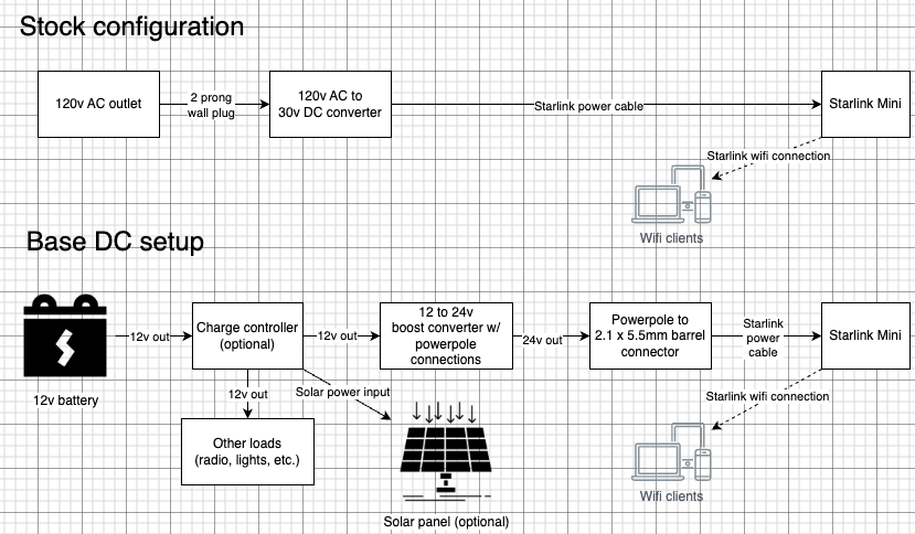
Power connection block diagrams for stock configuration and my base DC configuration
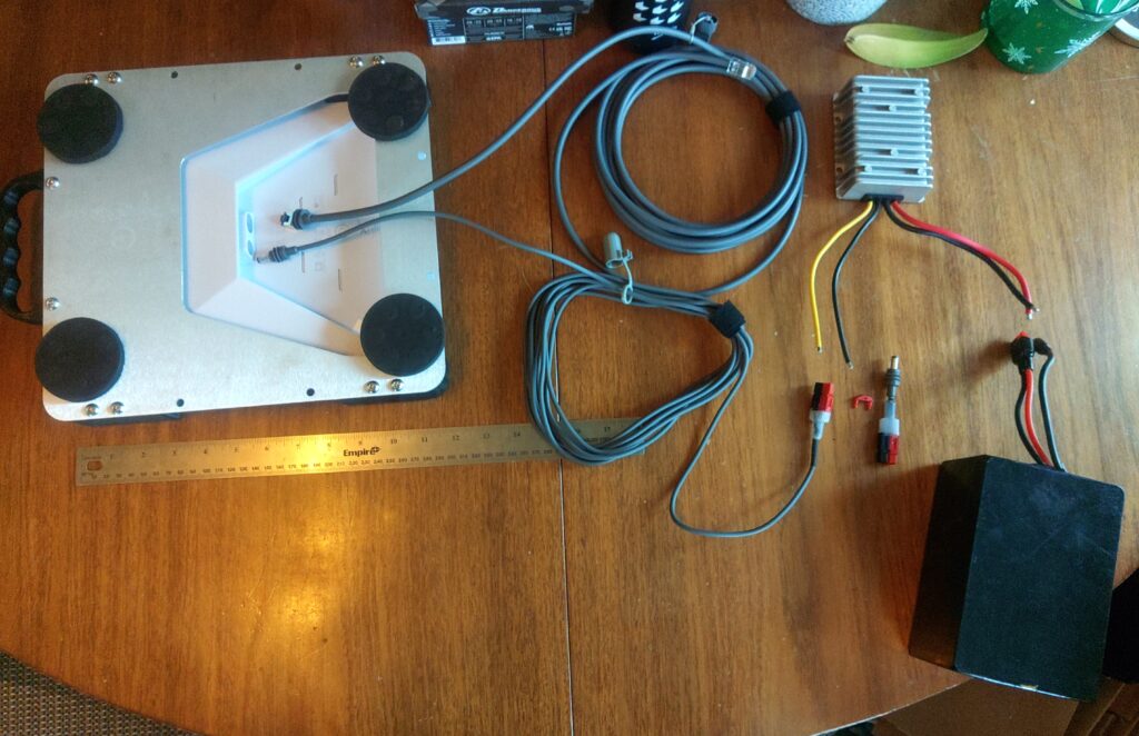
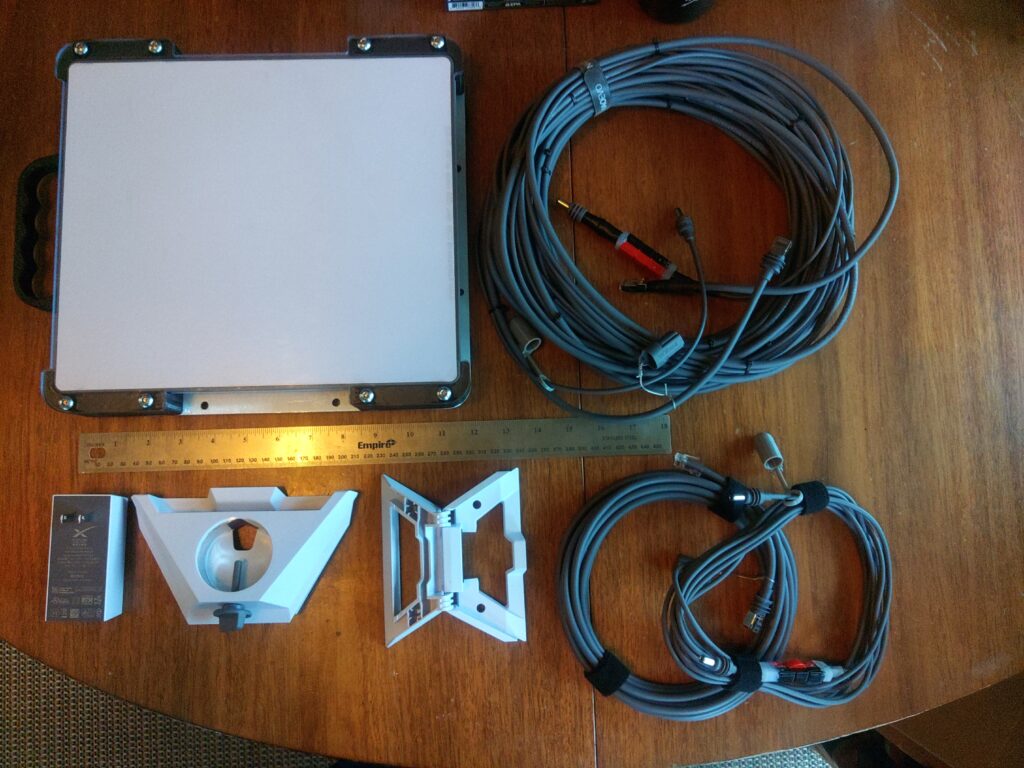
Exploded view of connections made in the base DC setup with the optional ethernet cable represented. From left to right, top to bottom is the Starlink Mini upside down showing the connection points, an ethernet cable with nothing connected to it, the DC power cable, 12-24v boost converter, and battery. It’s worth noting that the boost converter pictured here is for another project and is much larger physically and in terms of power capacity (20A) than the one used by me to run the device (10A) in the field and is there as an example.

Network in a box

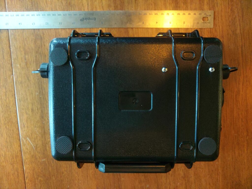
The network in a box is my solution for making the components that run the Starlink from a battery more compact, portable, and protected from dust and rain when in transit. Having all that set up ahead of time reduces the amount of time needed to fumble around making connections under duress or in adverse conditions and reduces the likelihood of human error causing damage to various components given the differences in voltage between the Starlink Mini and all other components. After dust and rain caps are removed from the ports it is no longer protected from the elements. There is a section that details the network in a box’s wiring, ports, etc. near the bottom of the post. The picture blow shows the system connected to power the Starlink, connect ethernet to the router included in the box, and has the optional ethernet connection to the laptop hooked up. Another advantage of having a separate network in a box is that the router running OpenWRT is more configurable than the Starlink Mini itself and supports features like firewalls and VLANs. These features can be important when integrating the Internet connection with an AREDN mesh node.
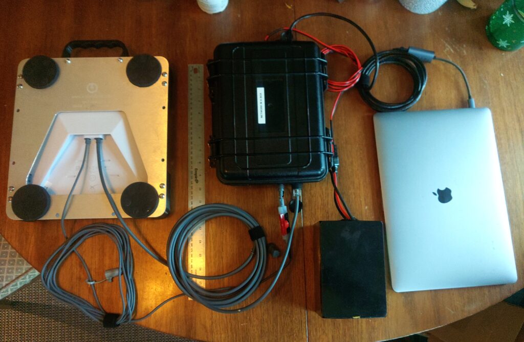
Optimizations, accessories, and considerations

Power consumption and snow melting capabilities

The unit tends to use about 25w of power at the unit (not including power used boosting the voltage) while running without the snow melt system running. I’ve intentionally disabled the snow melt functionality to prevent unwanted spikes in power usage. Most scenarios I’ll use the unit in involve me being outside or near the unit so clearing snow from the unit by hand shouldn’t be an issue. With the additional thickness of the protective polycarbonate layer and small air gap between the two I suspect the snow melting functionality would be less effective anyway.

Cable kits and cabling considerations

I have two power cables for the unit – one aftermarket 5m cable and the 15m cable included with the kit. The 5m cable is more efficient and has a lower voltage drop than the 15m one and can be used when the unit doesn’t need to be far from me to get a clear view of the sky. It’s also nice to deal with only 5m of cable unless you actually need the 15m length to fit your situation. These power cables are 2.1 x 5.5mm barrel connectors with a center pin positive configuration with weather resistant boots on both ends. I did splice powerpole connectors inline with the Starlink DC cable so I can connect directly to a 24v boost converter that has powerpole ends installed if necessary. It removes the need for multiple adapters in some situations, but allows you to connect to the native barrel connector in others.

In order to connect the unit to AREDN or any other network you might want to run that can’t run as a wifi client you’ll have to purchase a special weather hardened ethernet cable that has a boot that seals the port on the unit when the plug is removed from the port. I have an aftermarket 5m cable to match the power cable’s length and purchased a 15m cable from the Starlink website for about $30. This pairing of cables enables me to optionally connect the unit to a router or switch and can allow me to move the wifi access or cabled access closer to my work area which might be necessary if the position of the Starlink unit prevents a reliable wifi connection.

The official and aftermarket Starlink ethernet cables I purchased have proprietary RJ45 ends with a weather resistant boot that protects the jack from water and dust ingress. I ended up cutting one end off of each ethernet cable and installing a standard RJ45 end for compatibility with standard ethernet jacks found on most consumer routers and switches.

Protecting the unit from adverse conditions and adding additional mounting capabilities

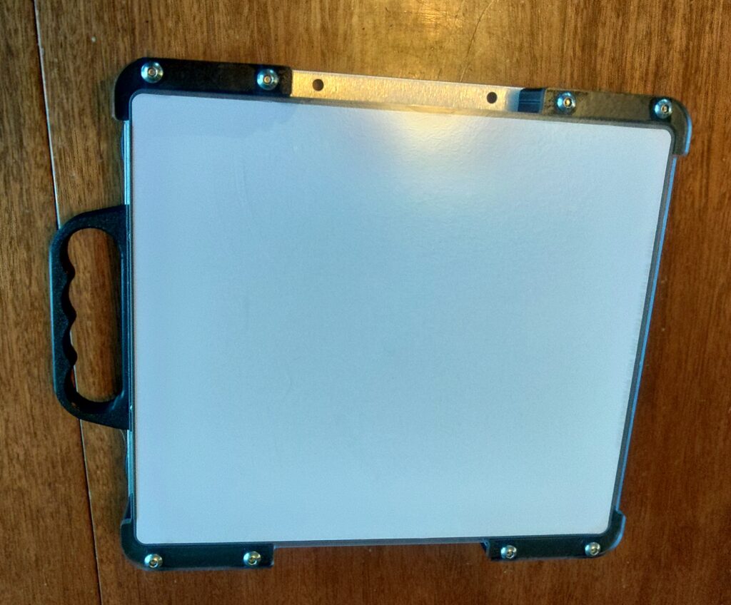
While it’s not explicitly necessary to deploy the Starlink Mini physically hardening the unit with an aftermarket case could also be useful in some situations and has some advantages, but has costs in terms of additional bulk, weight, and safety considerations in my configuration. The surface of the satellite terminal that faces the sky can be scratched, gouged, or otherwise damaged by branches or sharp objects. Third party manufacturers make cases for the unit that allow it to operate in rougher conditions than it was designed to and add some advantageous security properties along with additional mounting options.

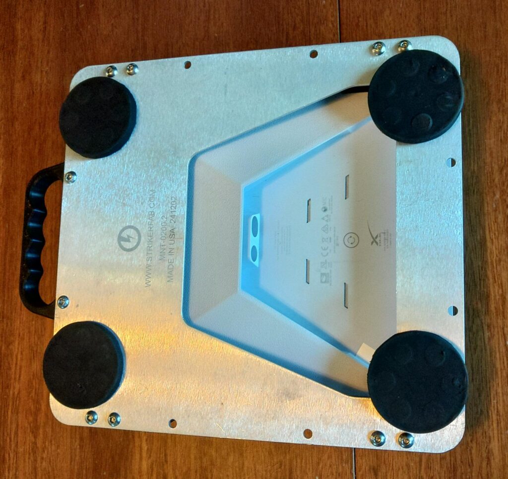
The case I purchased from Striker Fabrication has a handle, aluminum baseplate, and polycarbonate lid for the top of the unit. This allows me to mount it to my vehicle when offroading or on the highway as branches might sweep the unit or debris may strike it resulting in damage to the sky-facing surface. I added four 65 pound magnets with M6 threaded posts and lock washers to the corners of the unit that allow me to mount it to any magnetic surface such as a vehicle roof or hood. The holes I used to mount the magnets can also be used to bolt the case to any other permanent or semipermanent mount point using M6 screws. The aluminum plate under the case is compatible with the mounts that come with the Starlink Mini so it can be placed on a pole or on the ground with the included kickstand without needing to be removed from the case.

I can also loop coated wire rope through the aluminum and roof rack and secure it with a pad lock to ensure that a branch strike won’t sweep the unit off the roof of my vehicle entirely while in motion. It also acts as a theft deterrent for when the vehicle is unattended. I have two other pieces of coated wire rope that are 2.5 feet short of the full length of the power and ethernet cables to make theft of the deployed unit more difficult and to provide strain relief if the cable is pulled or tripped on when deployed on the ground. If the coated wire rope is anchored to a secure point on the terminating end a trip or pull on the cable is less likely to result in the power and network cables from being ripped from the Starlink Mini or attached power supply and network equipment. A pulled network or power cable can damage other equipment such as batteries, network hardware, or laptops by pulling them over or off of elevated surfaces. The Starlink unit will hopefully be the part that is harmlessly dragged by the coated wire rope due to its relative light weight and the other end of the cable being secured. The choice of coated wire rope was made because of its relative strength and light weight. The coating on the wire rope prevents scratches on painted surfaces, allows it to slip past snag points more easily when pulled, and aids in corrosion resistance.

Magnet safety warning: The four 65 pound magnetic feet provide a total of 260lbs magnetic pulling force. These will unexpectedly stick to metallic objects, pick up sharp bits of metallic grit and filings that can damage paint, and they will stick to metallic objects in your pockets or in your environment while being carried. Be aware of your surroundings and exercise caution. The magnetic mounts can also cause the case to crush your fingers when the case sticks to a metallic surface. Don’t ask me how I know. It’s worth noting that with this configuration it can be difficult to remove the device from a surface that it’s stuck to. Exercise caution when using powerful magnets – especially when handling the unit, sticking it to a surface, or removing it from something it’s stuck to. When it comes loose it does so quickly and you can unintentionally throw the unit when it releases. Again, don’t ask me how I know.
Factors effecting operation and Internet bandwidth

Internet connection speeds vary due to a number of factors including the location of the unit and whether or not it has a clear view of the sky according to its specifications, the number of users connecting to the satellites the unit is also using, and wifi connection strength.

Full kit photos

The following photos show the full kit. Most components of this kit are fully optional. The only real requirement to run the unit is the 12-24v boost converter and associated connections along with an activated Starlink Mini and a clear view of the sky. The picture shows the 15m cables power and network cables that are zip tied together every 18 or so inches since they’re almost always used by me at the same time, but the ethernet end doesn’t have to be connected if there’s a reason not to. The 5m cables are separate because I can usually use the Starlink Mini’s wifi at close range and handling more cable isn’t usually necessary but I have the option to deploy the second cable if needed. This kit includes aftermarket water + dust resistant caps on the Starlink end of all cables to protect the cables from water and dust during deployment and breaking down in adverse conditions. The bottom row on the left shows the AC power adapter, pole mount, and kickstand when opened, but not attached to the bottom of the unit. The pole mount and kick stand snap into the underside near the network and power cable ports and the enclosure is fully compatible with the mounts as well.
Base configuration and added router / AREDN node

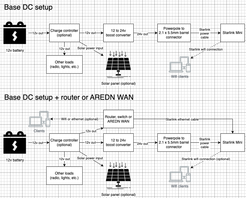
The following block diagrams depict a basic DC power setup with optional solar and battery charge controller as well as a configuration that connects the Starlink Mini to a router or AREDN node. Since AREDN nodes are functionally routers the connection principals are basically the same. See the above photo of the network in a box setup to see what the wiring looks like with a connected router.
Network in a box detail and photos

Exterior detail

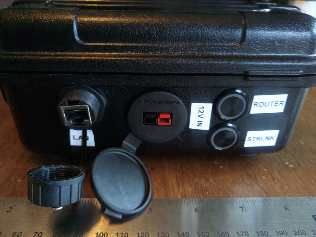
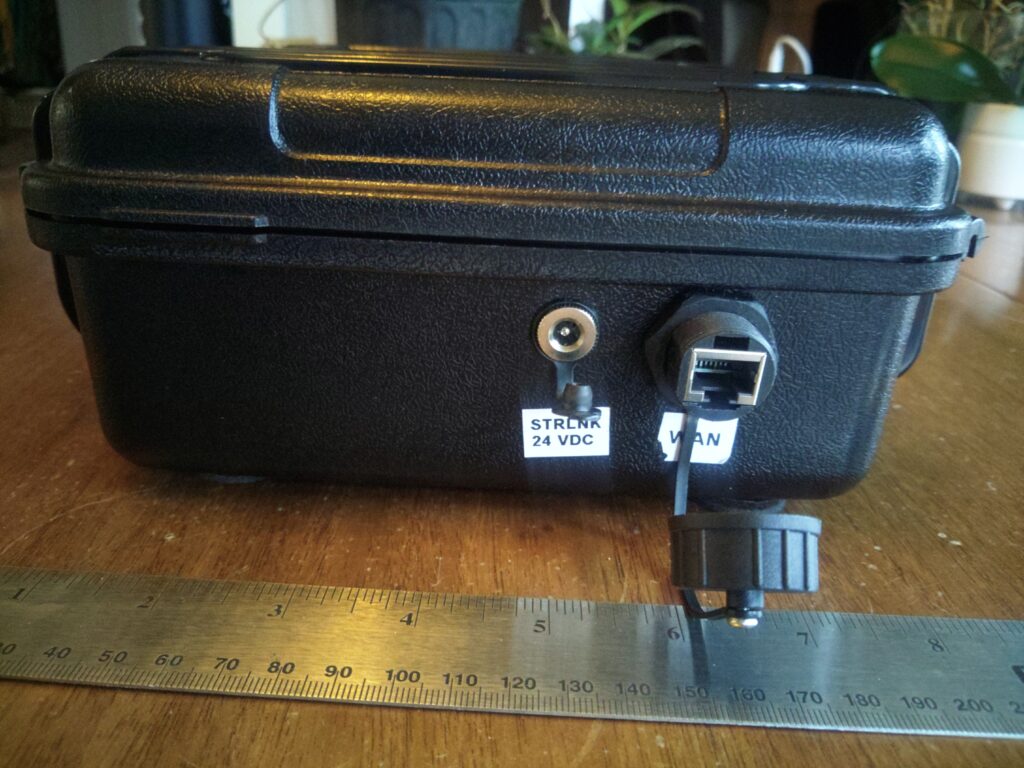
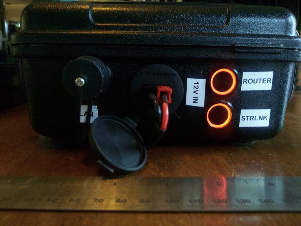
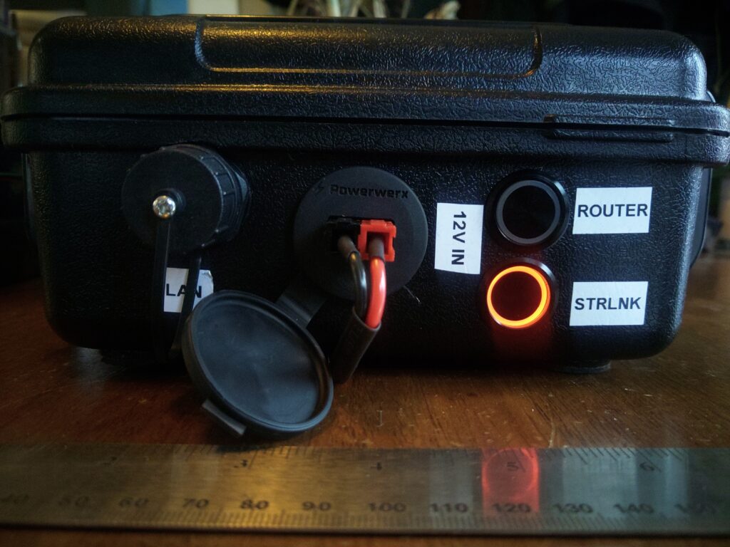
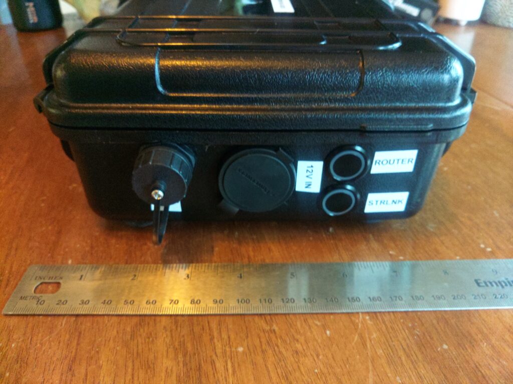
The gallery below shows the exterior of the enclosure including ports and power controls. As noted previously this unit has port covers designed to protect the system from dust and moisture in transit. Once the ports are opened the unit is vulnerable to dust and water ingress so it requires some care after being deployed. The bottom of the unit has non-slip pads stuck to it because the enclosure’s bottom is slippery and there is a chance the screws that hold the boost converter could scratch surfaces so those non-slip pads also provide a degree of separation between the screws and the surface the unit is sitting on.

Power is provided by a single powerpole connector wired in a right-hand-red configuration, and power to various components is controlled by two pushbutton switches with LED power indicator rings. These physical switches are installed for easy control of loads and to prevent parasitic power draw when components shouldn’t be running.
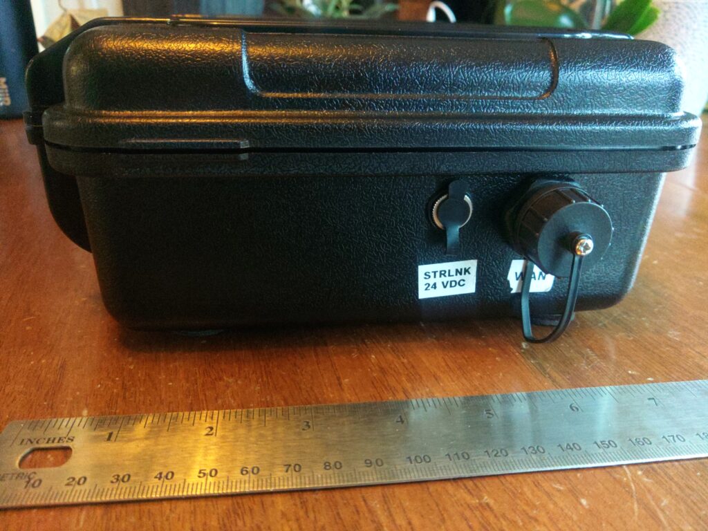
Interior detail

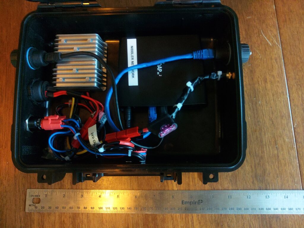
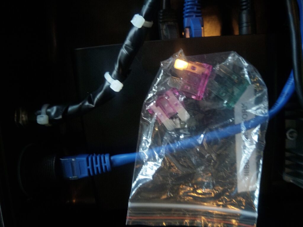
The inside of the enclosure is shown below. The major components are a DC 12-24v boost converter, a Mikrotik hAP2 router running OpenWRT, an open source router firmware, switches, fuses, power wiring, and network connections. The unit includes a bag of spare 1A and 3A fuses that are stored inside the case for field repairs. The router is connected to the bottom of the enclosure using velcro so it can be removed as needed. All power connections in the case are also powerpole so in the event some component fails and needs to be replaced, bypassed, or reused elsewhere on the fly there’s minimal effort, tools, and wire splicing required to make changes.
Starlink Mini network engineering details

The Starlink unit is configured from the mobile app, but the base networking characteristics of the unit are as follows:

  • The Starlink Mini has a built-in router and dual-band wifi access point as well as a weather-hardened proprietary ethernet connector that supports provides 10/100/1000Mbps ethernet. This connector is a modified RJ45 jack wired using the EIA 568B standard. The official Starlink ethernet cable is outdoor rated Cat6 shielded twisted pair.
  • Starlink service provides native IPv4 and IPv6 capability.
  • There are 2.4 and 5Ghz wifi networks generated by the unit itself and these can be disabled or split into different SSID based on frequency if required for certain devices that have issues selecting the correct network.
  • The unit is configured to hand out IPv4 and IPv6 addresses using a local DHCP server runing on the Starlink Mini when it’s in the default operating mode (not in transparent bridge mode).
  • The default IPv4 address space is 192.168.1.0/24 and the built-in router uses 192.168.1.1 for its address and the default gateway.
  • I don’t think there is any web UI to configure the router on the Starlink Mini. This isn’t the case with other Starlink products I’ve worked on. The mobile app or Starlink website is required to configure the Starlink Mini.
  • Access to GPS location, telemetry data, and configuration endpoints are available via gRPC endpoints hosted on the Starlink Mini unit. These gRPC endpoints may also be the mechanism that the app uses to configure the device. See Sparky8512’s project for example code that interacts with the gRPC endpoints.
  • Unlike its predecessors it can’t be powered using power over ethernet. The DC power cable is required for the Starlink Mini to power up.
  • The unit can be set up in transparent bridge mode and any wired device connected to it is required to run its own DHCP client to get a WAN address from the upstream Starlink network. In order to switch back from transparent bridge mode the unit will have to be factory reset using the reset button on the under side of the unit.
  • All wired and wifi hosts connected to the unit are dropped onto the same subnet and can communicate with each other directly. There doesn’t appear to be any client separation inside the LAN.
  • The advertised WAN bandwidth is up to 100Mbps but I and others have seen speeds in excess of 100Mbps in certain locations and conditions.
NET Net notes – DC electronics safety (07/21/2024)

DC electronics safety notes

* Why are we talking about this?
* Personal safety
* Fire safety
* Preventing catastrophic equipment failure
* Wire gauge - sizing wire correctly
* Measured in AWG, bigger numbers are smaller wire
* Many wire manufacturers will provide an "ampacity" chart to talk about current rating in various wire products.
* Wire construction
* Stranded wire is easier to work with generally but isn’t as good of a conductor as solid wire. Stranded wire is also best for applications where the cable is expected to bend and move.
* Solid wire is harder to work with but has higher durability and is a better conductor than stranded wire. It’s best for applications where the cable won’t be moving a lot such as fixed installations and is generally cheaper.
* Copper wire is more expensive and is a better conductor of electricity and tends to be more durable.
* Aluminum wire is half as heavy but requires heavier gauges to carry the same amount of current as copper wire.
* Sizing wire to not be the thing that gets hot when a short circuit occurs.
* Overgauging for expected load relative to fuses or breakers to ensure the wire isn't the thing that heats up and burns.
* Fuses and breakers
* Why fuses?
* Burn out and stop the flow of current with a fusible link.
* Affordable
* Keep spares
* Why breakers?
* When the heat of an internal element is too high the circuit is broken by an element. Circuit breakers can be reset.
* More expensive than fuses.
* Automatically resetting circuit breakers exist, but many are manual and can be used as a switch to turn sources of electricity off.
* Note: When building DC systems make sure circuit breakers are explicitly rated for DC systems. AC breakers aren't an acceptable substitute here.
* Install these items as close to the thing being switched as possible.
* Covering contact points
* Why cover contact points?
* Prevents accidental shorts by having less exposed surface area.
* Cover contact points
* Wire nuts
* Electrical tape
* Heat shrink
* Quality splices (mention marine grade)
* Connectors
* Powerpole
* SAE connectors
* Keeping things dry/sealed
* Because metallic dust and water can potentially short internal parts
* Using and understanding the limitations of various sealed enclosures
* Using properly built installed sealed connectors
* Use cable glands
* Silicon / sikaflex
* Power source disconnects
* Batteries
* Solar panels
* Avoid deep discharge of batteries
* Some sort of monitoring of battery capacity used
* Varies by battery chemistry

Solving a dorky problem – writing things down

Greetings, it’s been a while since I’ve written a post. I’ve had some things cooking in the background and have a few posts to write about some things I’ve been doing that aren’t especially interesting but could be helpful none the less. This post is about something that seems a bit silly, but is actually pretty important… the ability to easily and comfortably write things down while operating in places without writing surfaces.

I ended up stumbling across something that pilots had been using for quite some time: aviation kneeboards. The advantage of these is that they’re designed to be strapped to a leg and for situations where space is constrained like a cockpit. This concept maps nicely to vehicles or any spot where you can lay down in a supine position and bend a leg or sit. Most situations I’m in when operating in the wilderness it’s nice to not have to deal with a folding table when I’m in an odd spot or simply don’t want to carry one on a hike. As long as I can sit in a relatively normal position or lay in the back of a vehicle or on a bed it’s easy to use.

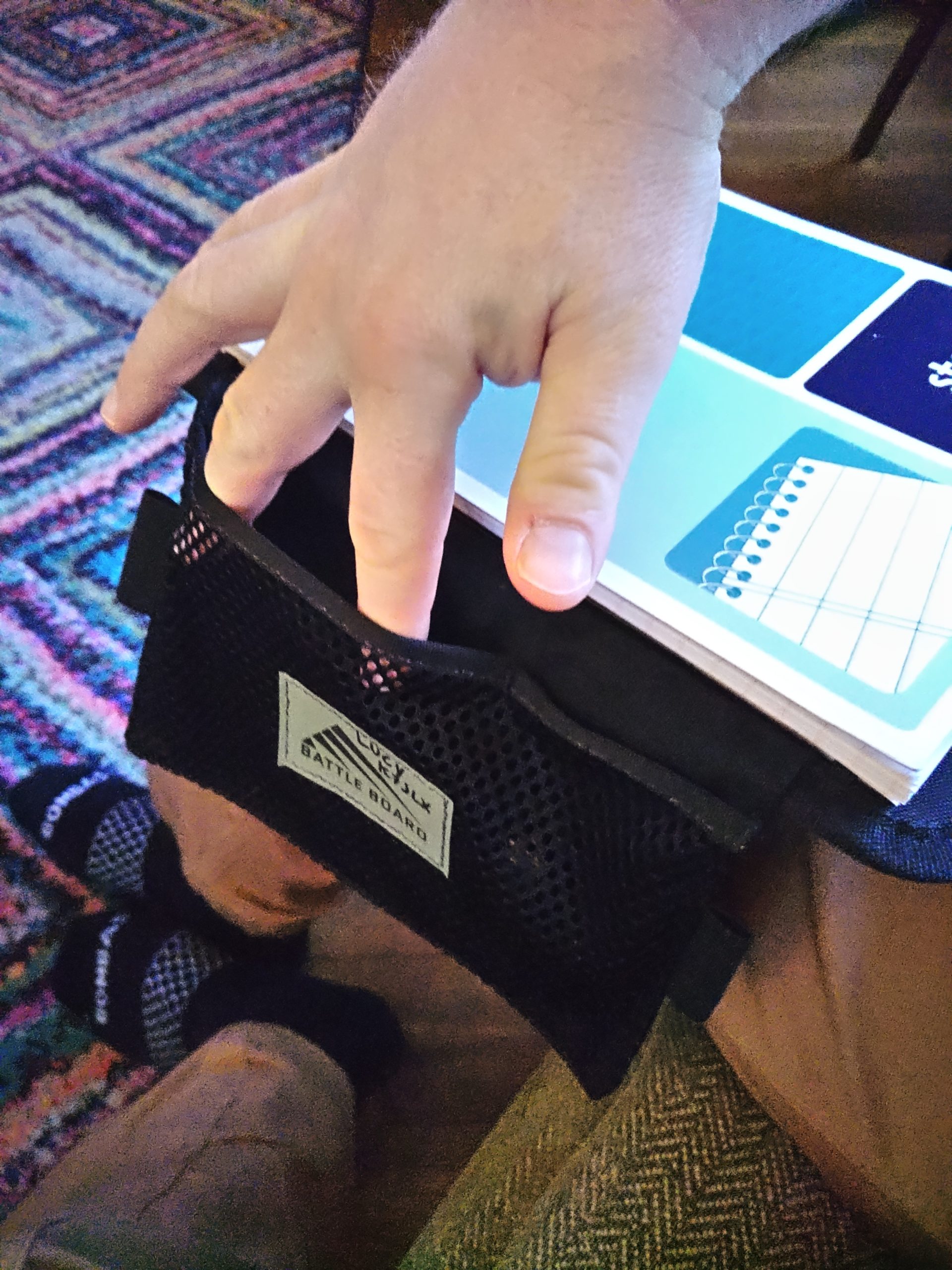
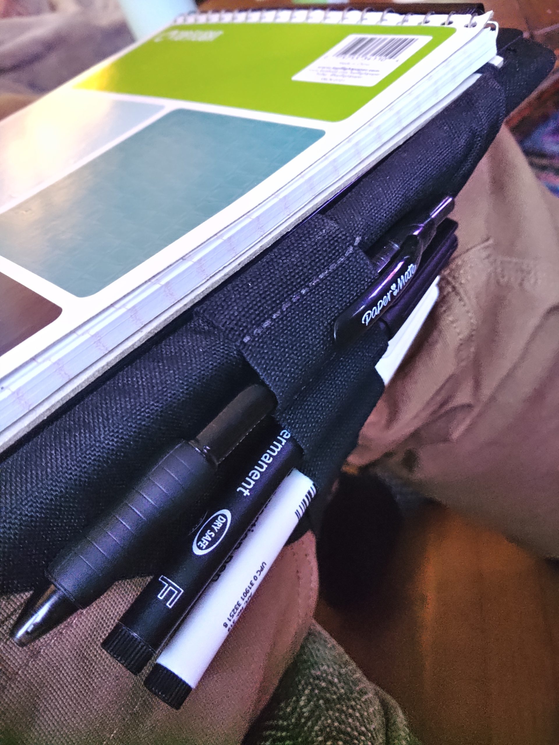
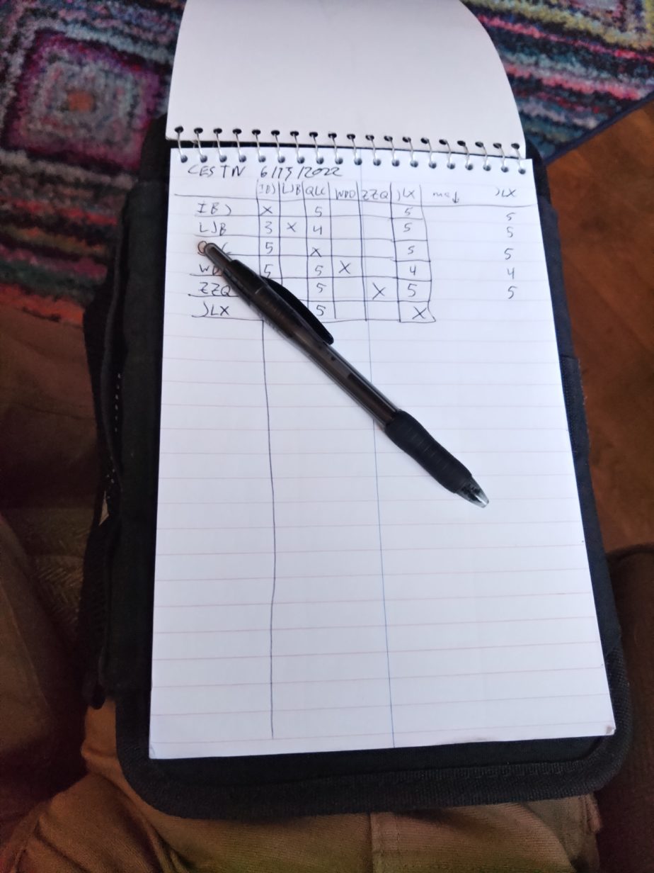
It was useful to have something big enough to easily record dozens of callsigns for one weekly net I participate in. It’s easiest to track all the participating stations’ callsigns on a single sheet of paper for easy counting and reference. A 6×9″ tablet had been working for me previously so I sought out something that could accommodate one. A company called Battle Board made a “medium” aviation kneeboard that could hold the tablet I was using. I picked this one for a number of reasons including a clipboard attachment that can be used for other kinds of documents, markers for the polycarbonate window that can be erased, and a plastic sleeve that can be used to protect maps or other documents from water. I suspect any similar device could work just as well, but this one could be used for other things I’m interested in doing.

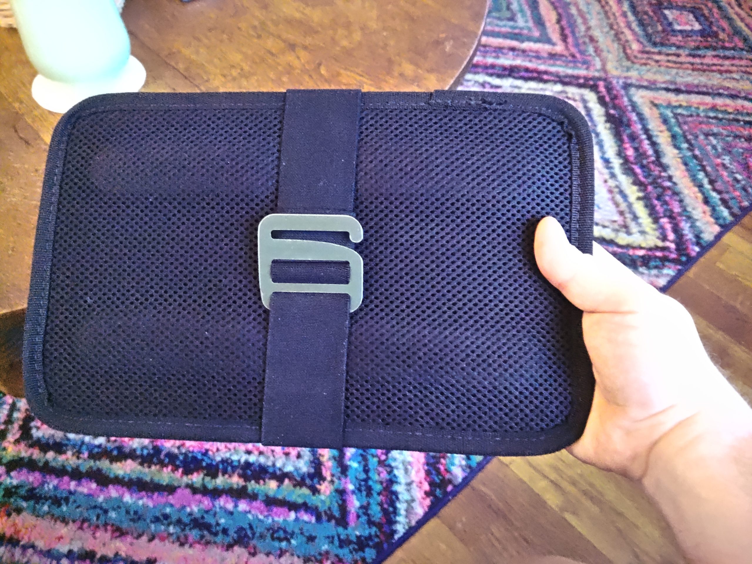
This works by setting it on top of your leg and pulling the elastic band behind it and attaching the adjustable metal hook to some elastic bands on the back of the cloth flap with the mesh pocket. I’ve used this in a number of locations from bed with a bent leg, in a vehicle, in a camping chair, and sitting on large rocks. It works pretty well and easily slides into a backpack. It’s pretty comfortable and does a reasonably good job of staying put. There are elastic retention straps that easily secure the top and bottom of the tablet using the cardboard backing. The mesh pocket on this specific one can be used as a phone holder. It also holds a ‘rite in the rain’ notebook so it’s still useful in inclement weather.

Estimating power consumption for your equipment

Hello everyone! Today I wanted to post about a topic that is pretty important if you have an interest in off grid, grid down, or emergency communications: estimating power consumption for your equipment. This post is in part inspired by a topic I chose for the Portland Neighborhood Emergency Team chat net. Shortly after I chose this topic I got an e-mail from Kevin, N6KVN asking for some advice for setting up a portable field station, and so I figured I’d write a more detailed post about my methodology and way of thinking about operating a ham radio station when grid power isn’t available from a preparation or pre-planning standpoint.

My basic test setup consists of three components. I have a power source of some kind. This could be a battery or a wall-connected power supply. The next component is a power meter connected between the load(s) and the battery. This component actually does the work of measuring power consumption. The final component of the test setup are the loads you wish to test. It’s important to make sure all the components in the setup are rated for the amount of current you expect to draw during testing. You can usually find that in the specifications of each individual component. You add those up and make sure your meter is rated for that much current and that your power supply can supply all of the required current. All the wiring in between should also be properly rated for that amount of current.

Example lighting current draw test

Example test setup

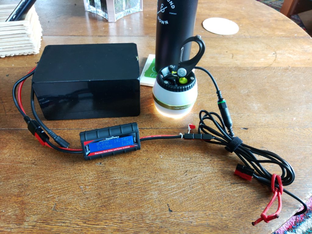
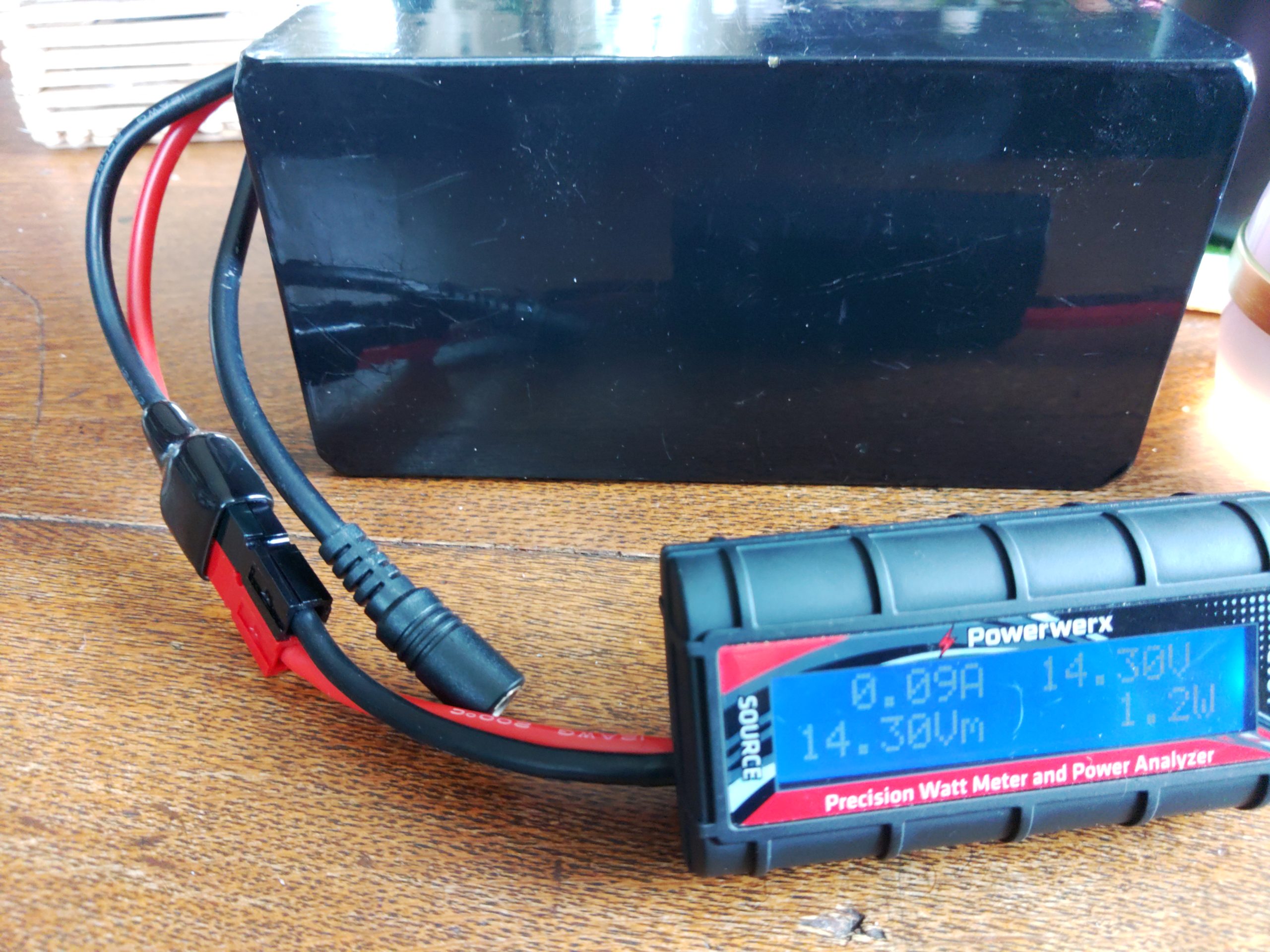
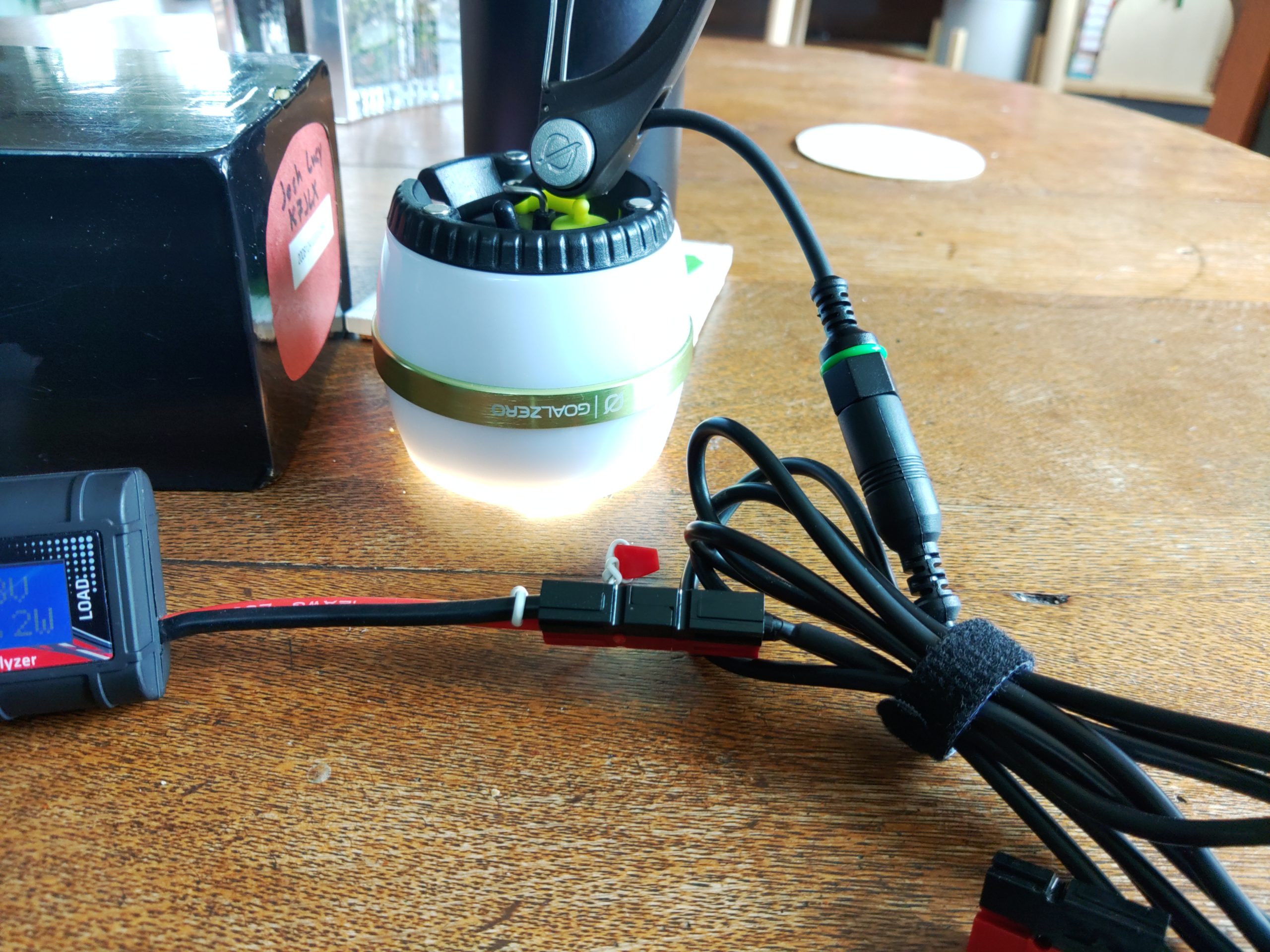
In this example I demonstrate testing a lighting device that runs on 12V and explain my methodology for hooking everything up and how I use back-of-the-napkin math to estimate power usage and requirements. In the above photo we have all three of our components for this specific test – a power source which is a battery in this case, the Powerwerx inline DC power meter, and load which is an LED lamp whose power usage I want to characterize. The Powerwerx inline meter supports a lot of measurements but in this post I’m going to mostly focus on current drawn and Ah, or amps per hour.

I started by connecting the power source to the “source” side of the power meter and then connected the load I wanted to test to the “load” side of the power meter. The images above show the light on but I will usually measure power with all the loads turned off to see if they draw current in the “off” position. It’s pretty common for devices to take a small amount of power even while off. This is called a parasitic load. The specific LED lamps I wanted to test have three settings: off, low, and high. I tested off and my power meter registered no current consumption. That’s probably because these lights have a hard off switch.

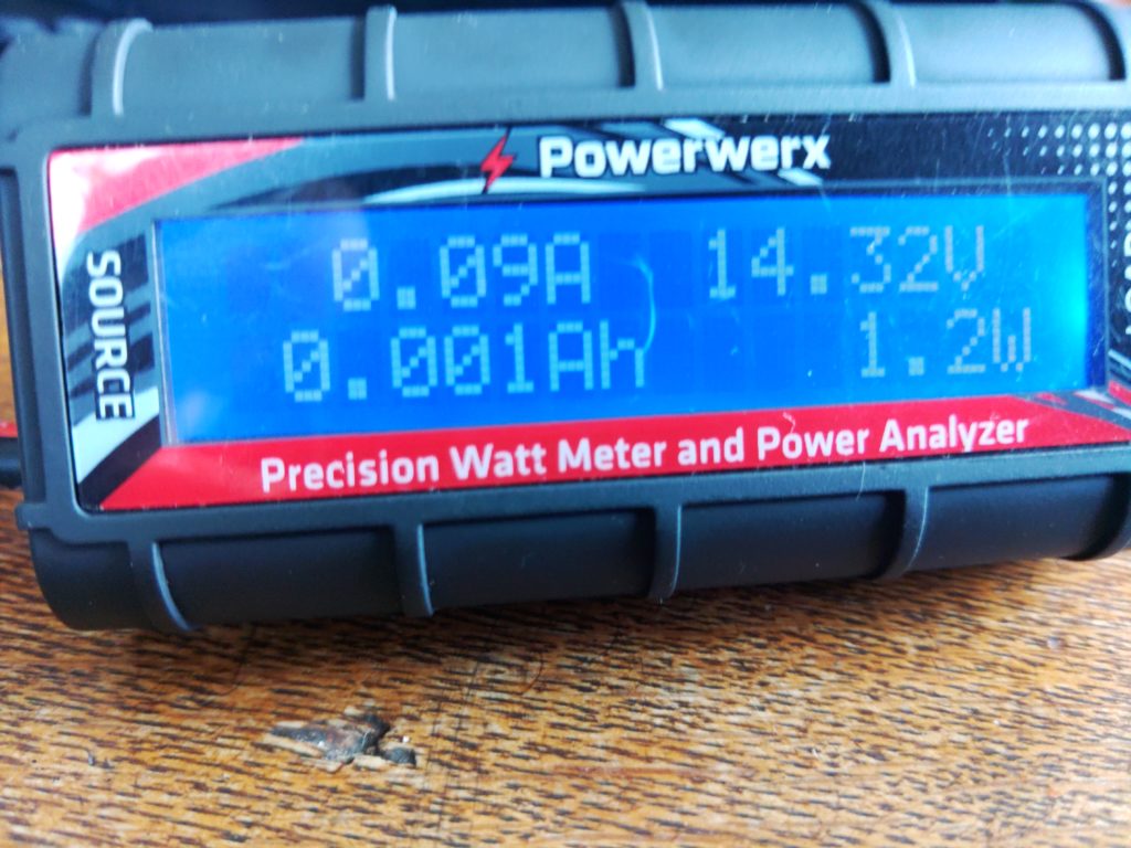
Power consumption with the switch in the “low” position

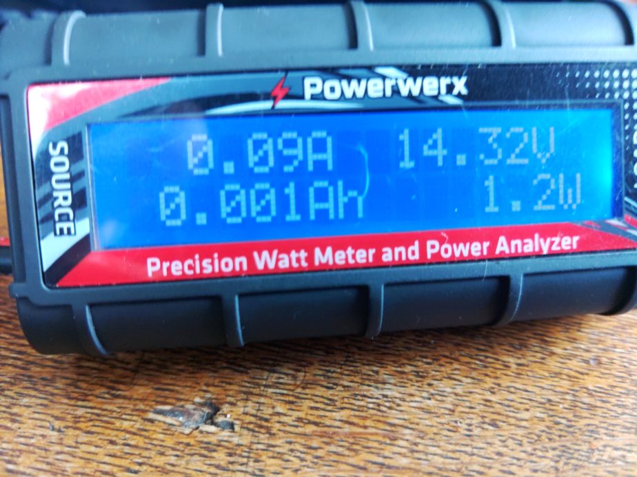
As you can see here this light draws 0.09A in the “low” position. If we were to run this device for 1 hour it would take 0.09Ah (amps per hour). You might have also noticed that there’s a measurement reading 0.001Ah. For this specific meter that means we’ve used 0.001Ah since the meter was connected to a load. There will be more on this measurement later.

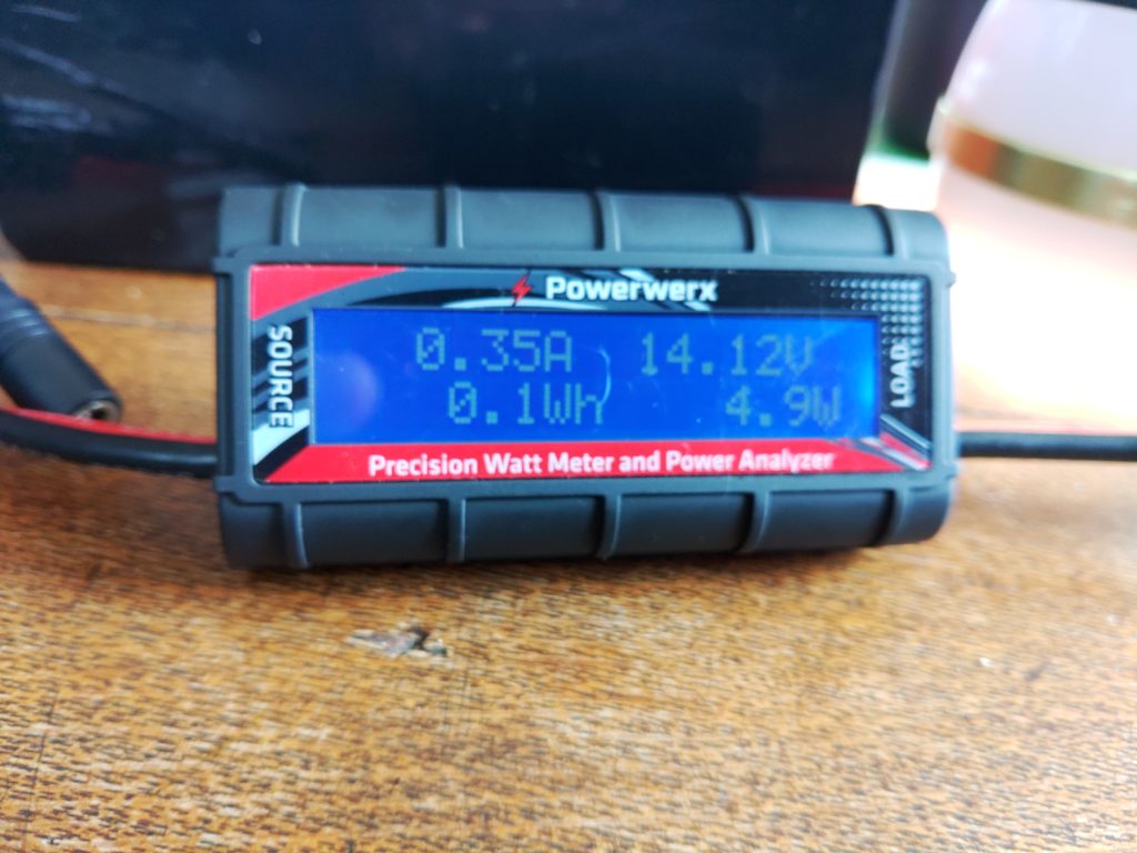
The LED lamp with the switch in the “high” position

With the LED lamp in the “high” position it’s drawing 0.35A of power. With the information gathered so far I can estimate how much power I’ll need if I want to run this light for a certain amount of time, and I can figure out how much power I can expect it to take while it’s running. If we use the Ah reading I mentioned earlier we can also understand how much battery capacity we’ve used since the last time the meter was restarted. Let’s start with that since I mentioned it.

To determine how much battery we’ve used as a percentage I’d use the following formulas:

battery capacity used as percentage = battery capacity / battery consumed

battery remaining as percentage = 100% – battery capacity used percentage

For a theoretical battery with 20AH of a capacity and 2Ah consumed the formula looks like:

20AH / 2Ah = 10% capacity used

100% – 10%= 90% capacity remaining

Now let’s add time to the mix. I’m going to use a Yaesu FTM-100D radio as an example of thinking about how much power it will use based on the specifications from the manual. According to its specifications when it’s receiving only it’ll draw 0.5A. The max power it will draw when transmitting 50W on 2m is 11A. Using this information let’s figure out how much battery we’d need to operate this radio some percentage of the time for 8 hours. For the purposes of this post we’ll call the amount of time we’re transmitting our duty cycle. We’ll assume we’ll be transmitting at 50W for 10% of the time that the radio is powered on. The formula will look like this:

Ah used = current * hours * duty cycle

While the radio is receiving only during an 8 hour operating period we’ll use 3.6Ah of battery capacity:

0.5A * 8h * .90 (90% receiving time) = 3.6 Ah capacity used

Now we should compute power usage when transmitting at 50W:

11A * 8h * .10 (10% transmitting time) = 8.8 Ah capacity used

Total power consumption over 8 hours for the radio:

3.6Ah (RX only) + 8.8Ah (TX at 50W) = 12.4Ah

When we add them up we need at least 12.4 AH of battery capacity to run that radio for 8 hours while transmitting 10% of the time. If you want to run the radio for 16 hours transmitting 10% of the time you’d either need to be able to re-charge that battery to replace the discharged power before the battery gets too low or have a battery large enough to run the radio for 16 hours, meaning you had at least 24.8 AH of battery capacity. There’s also a way to cheat on battery capacity. If you can reliably charge your battery as you run your radio from a source like a solar panel you can replace current that’s drawn down by your loads. In that case you’d just subtract the current you’re able to supply from your charging source from the load. If you end up with 0 or a negative amount of current draw you’re able to power your radio without discharging the battery.

Figuring out how much power you use as you go

This section can apply to both bench testing and operating in “the wild”. This details how you’d use any power meter that’s capable of measuring cumulative power use while you’re running loads. The Powerwerx meter I mentioned earlier and the BuddiPole PowerMini have this capability. If you connect one of these power meters inline with your setup as you operate and run loads it will add the cumulative power drawn. This can be useful when you want to understand how much power you’ve drawn down on a battery. As I write this before the 4/3/2022 Portland Neighborhood Emergency Team chat net and NET net I plan to operate on battery with lighting during the net and record my power usage here later, but the thing I do is the following for both bench testing and off grid measurements:

  • Connect my power meter between the power source and load as described above
  • Perform whatever activities I would normally perform
  • When done I check the consumed Ah on the meter to get my battery capacity used
  • Calculate battery percentage used

Formula for calculating battery capacity used:

battery capacity used / battery capacity = percentage capacity used

For an example with a 20AH battery and 15Ah of capacity used during some activity I would have 25% capacity remaining on the battery. I can use this formula in the lab to estimate how much power I’ll need in the field later, or understand how close I am to drawing my battery down in the field:

15Ah / 20AH = 75% used battery capacity

100% – 75% = 25% remaining battery capacity

Adding it all up

When you perform this kind of analysis on devices you expect to run off of battery in the field you can begin adding up all your field components and understanding what your power requirements will be. If you know your lighting will take 2Ah to run for a few hours at night and 12 hours of radio operation might cost 13.2Ah you can say your station will take 15.2Ah to operate for 12 hours. As you add more devices such as phone chargers, laptops, etc. your power requirements will change. You can also use this methodology to reduce power consumption. For example if running your radio at 5W is sufficient to achieve your communication goals you could save a lot of power, requiring a smaller battery, or less recharging capacity. You could also achieve similar results by having fewer devices or keeping your radio transmissions more brief (decreasing your duty cycle). Comparing the sums of power consumption between different setups can also help you inform either your expectations of how to operate or what is possible with the setup you have. It can also help you right-size a battery or recharging system for your specific uses.

A real-world example

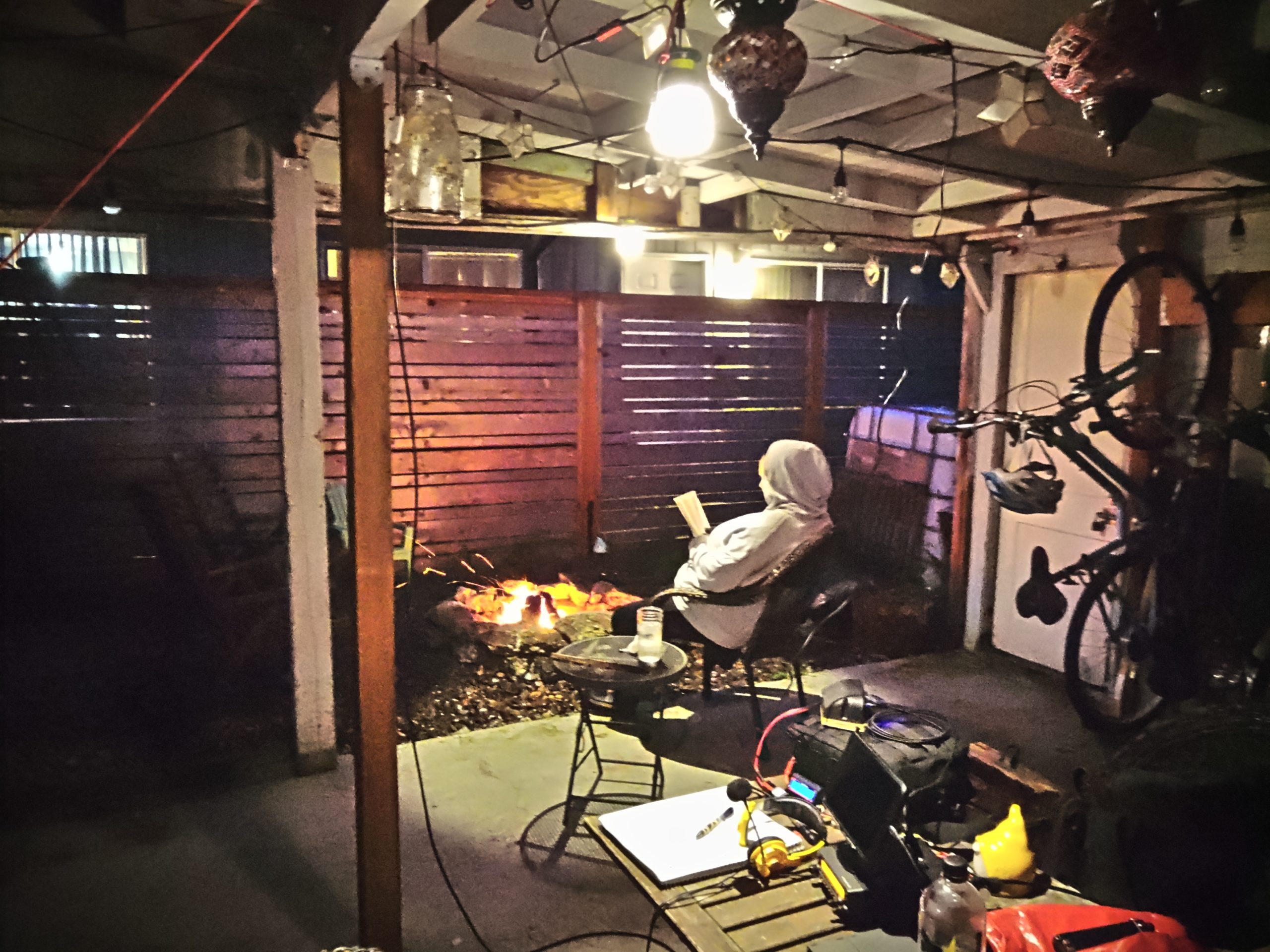
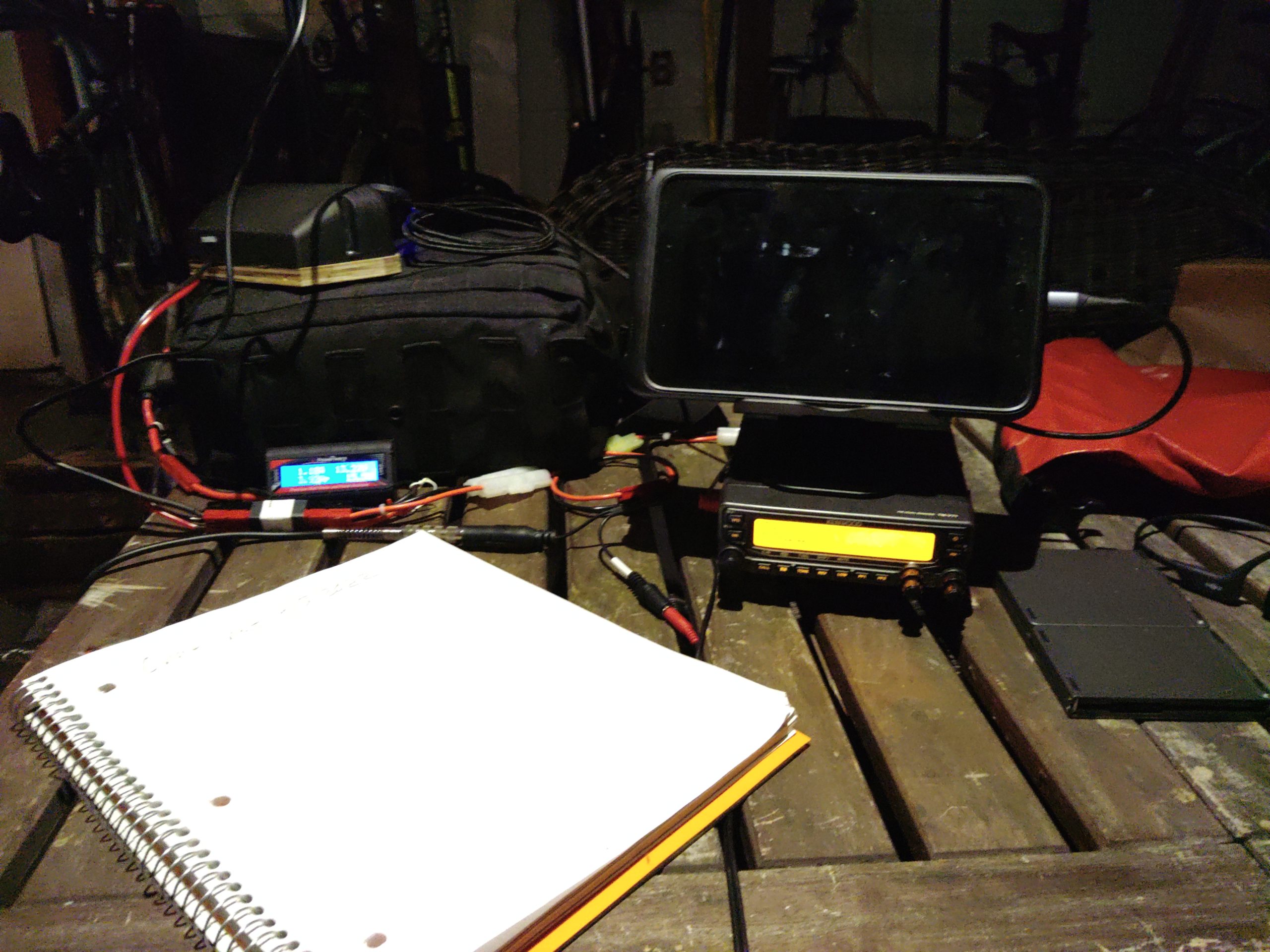
I wanted to add an update with another example of operating the radio in reasonable conditions doing a specific task that isn’t entirely theoretical, or just on-the-bench testing. Tonight I was net control for the Portland Neighborhood Emergency Team chat net, and I also participated in the Portland NET net as well. For most of the nets I was running two LED lights and I topped the last 25% of my tablet’s power off. I ran my Kenwood TM-V71A at 5w which drew about 3A when transmitting and 0.55A receiving. Both of the LED lights were set on low and consumed 0.1A apiece. The charger’s power usage varied depending on the part of the charging cycle the tablet was in, but at the end of 3 hours of running the radio, and about 2 hours of running both lights I used a total of 3.42AH of battery capacity. The battery I was using has a rated capacity of 40AH, so I used about 8.6% of its capacity (3.42AH used / 40AH of battery capacity = 0.086) doing both nets and listening on the first net’s frequency for an hour before it began. The first net that I was transmitting more on used the majority of the capacity, about 2.3AH. During the second net I only used about 1.1AH because I spent the vast majority of it listening as we ran lights and the tablet charger.

Tying it all together

By the end of this blog post I hope you came away with a good understanding of how I approach understanding and estimating my power usage and right-sizing my equipment for specific uses. This approach also helps inform how I operate when I don’t expect to have reliable power or when my situation changes and I’m not able to recharge batteries, etc. It can also show you how big of a difference it can make when you transmit less or when you add or drop devices from your setup.

This pattern can potentially be applied to other equipment like medical devices that can be run on battery. I’ve used the same method to profile my partner’s CPAP machine’s power consumption with various settings. I’ve been able to determine what sort of battery and charging system that will be required to keep it running when grid power fails or is unavailable (hint: turning off the humidifier and tube heater really saves a lot of power).

Notes after the fact

On the advice of Kevin, N6KVN I’m going to add a note about batteries. While this bit of the post is a bit out of scope it’s important to touch of the strengths and limitations of various battery technologies. Some batteries can be damaged by discharging them to 50% and others can be discharged to 20% or possibly lower before damage occurs. It’s important to understand the characteristics of the equipment you’re running. If you’ve read other posts of mine you’ll notice that I field a lot of LiFePO4 batteries. One of the reasons (apart from weight and other safety factors) that I tend to use them is because they can be discharged to a depth of 20% of remaining capacity before they’re permanently damaged. Most common lead-acid battery tech (think car batteries) can only be discharged to 50% before permanent damage to the cells occurs, but they are much cheaper than lithium batteries. Comparisons of various battery types is an entire post of its own, but these things are worth mentioning as you size your system and plan for the amount of energy you expect to discharge or plan to use. As an example my 100AH battery really has a usable capacity of 80AH because if I were to discharge the battery to 20%, or 20AH it would cause permanent damage to the battery (100AH capacity * 20% limit = 20AH, 100AH capacity – 20AH limit = 80AH of discharge before damage). This information should be listed by the battery manufacturer. If it’s not included I’d recommend reaching out to their support team.

APRS test from Stone Tower in Montpelier, VT

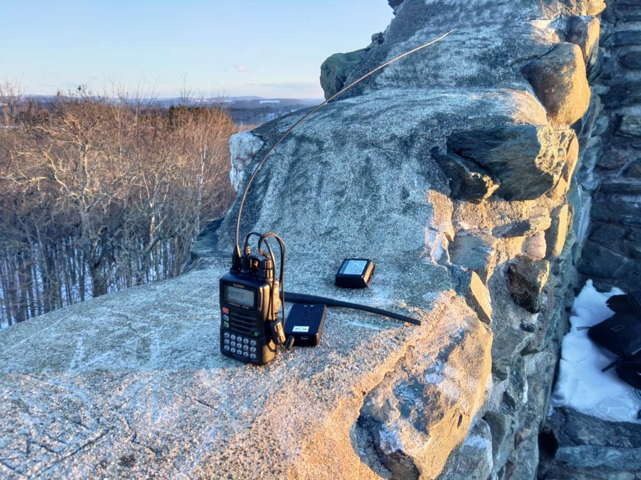
During a small road trip through Montpelier and Burlington VT Jen and I decided to stop at Hubbard park to go for a walk and try some radio nerdery. I failed to get pictures on the beautiful snowy walk through the park, but it was wonderful and near sunset. I ended up trying to use my Yaesu VX-6R and Mobilinkd TNC3+ to send position reports, and was ultimately successful from the top of the tower we climbed.

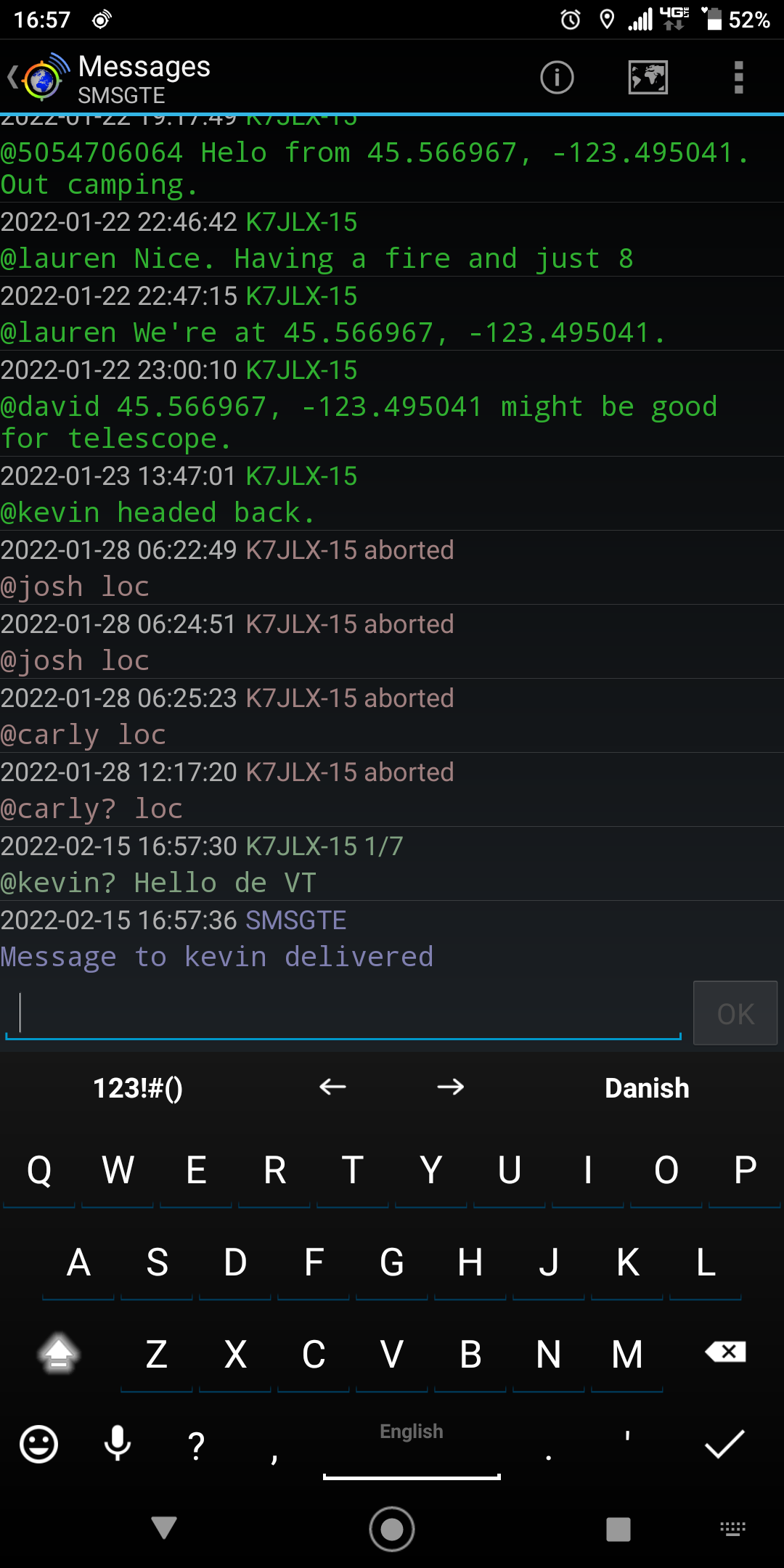
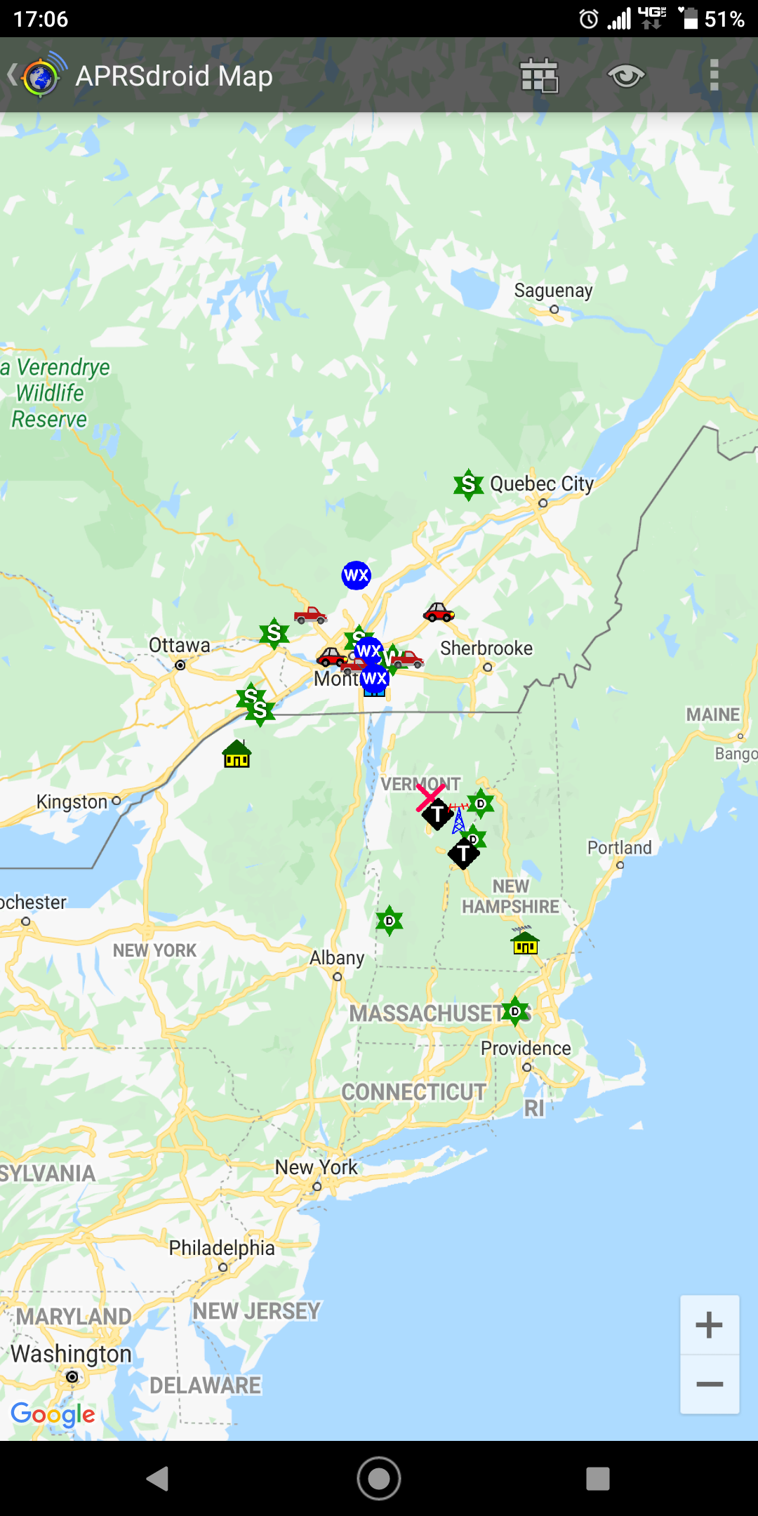
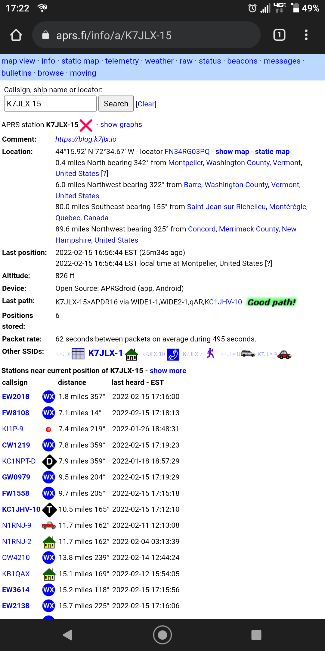
As you can see from the screenshots above I was able to receive a bunch of stations from the tower and was able to get out a position report as well as some SMS messages via SMSGTE. Oddly I never got ACKs for my messages, but I did get a reply from SMSGTE as expected when using the “?” after the destination call. The previous messages were from tests.

As you see from the screenshots I did finally have some success sending messages from the VX-6R, but it’s not as reliable as I’d like. There’s some work left to go. As a side note I did eventually get some bi-directional messages going through SMSGTE that aren’t shown in this screenshot with Kevin, K7AJK. With enough elevation I was able to overcome the shortcomings of this setup. In the screenshots my call is K7JLX-15 and the icon I’m using is a red “X”.

A woman stands in front of a low stone wall overlooking leafless trees and mountains in the distance with a mostly clear sky. A handheld radio and some parts are laying on the stone wall behind her.
On top of the tower with Jen looking north.

Attempting HF QRP operation in NE VT

Howdy! This post is one that’s been in the drafts list for a hot minute, but I took a trip to NE VT to visit a partner and on valentine’s day we went out in the woods behind her place to radio for a couple hours. After a hike that seemed much longer up hill than down we arrived a higher spot with a clearing that would allow me to set the Superantenna up. I wanted to test my new Yaesu VX-6R with a Mobilinkd TNC3+ for APRS operation. I was hoping to make some contacts with Canadian stations since I was less than 1.5 miles from the border on the hike, but alas I don’t have something set up right.

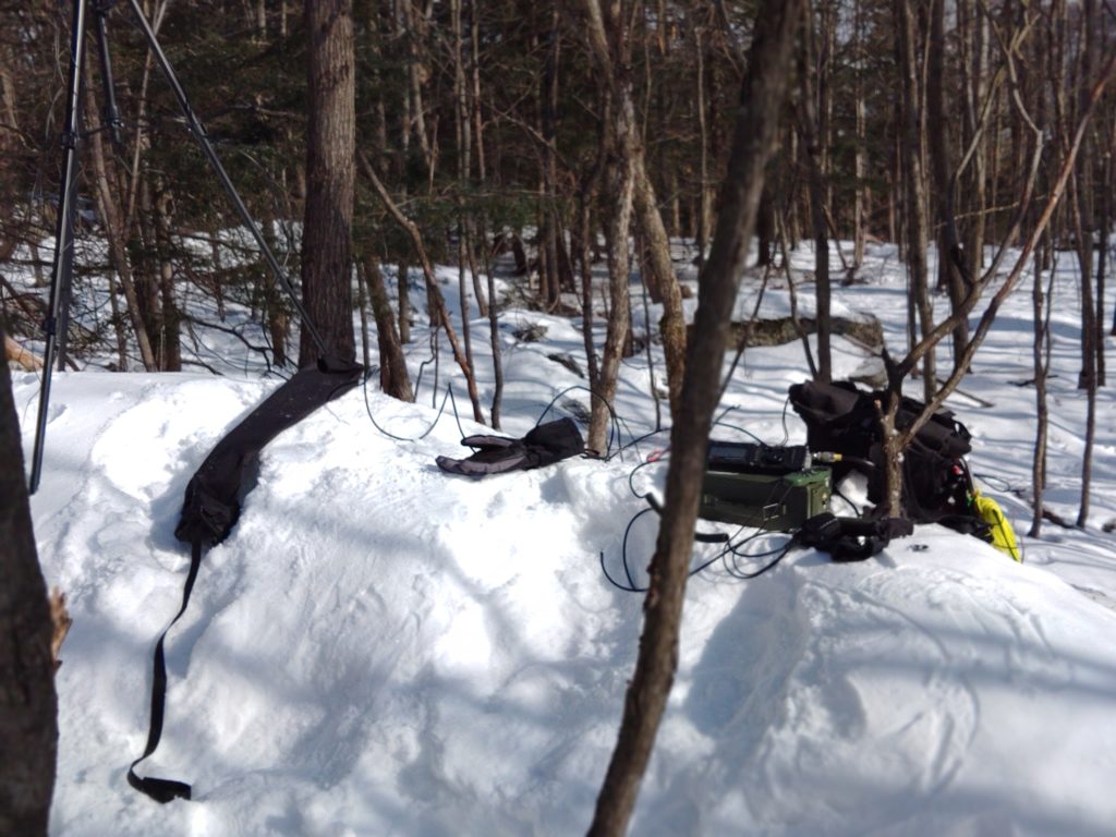
To add a bit of fun the shoulder strap on the Superantenna bag failed as seen in the photo below as we hiked up. Unfortunately that meant we had to hand carry the unit up and back down.

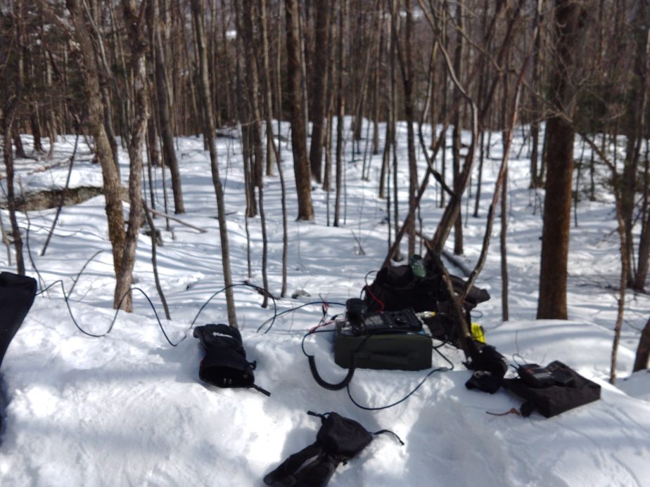
Radio equipment and a glove sitting on top of a snow bank in woods with deciduous trees and brush in the background.
QRP station set up in the woods of Northern VT
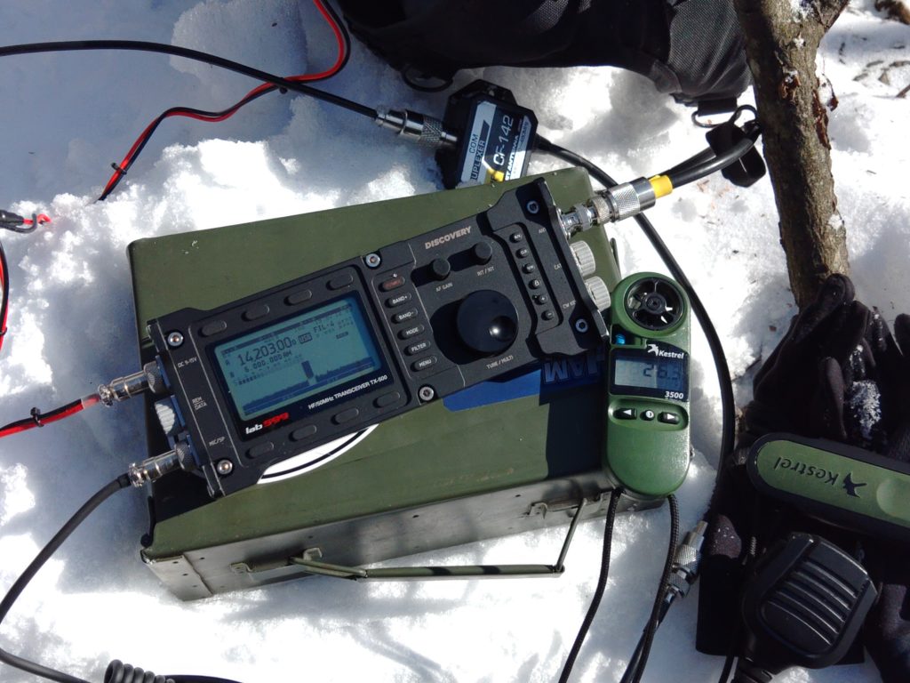
A Lab599 TX-500 radio sitting on top of an ammo can with a Kestrel portable weather station reading 26.3F. The radio is connected to a duplexer which is laying on the snow.
HF radio set up for 20m in 15-20F weather depending on the cloud cover.

After getting the setup ready to rock I tried some phone operations on 20m SSB, but was ultimately not able to make any contacts despite being able to hear a number of other stations. There was a contest going on so it was hard to reach other stations. I haven’t been having a lot of luck with the Superantenna lately apart from using for SWL. I kept the 4.5AH Bioenno battery wrapped in a warm shirt within my black Chrome bag to keep it as warm as possible rather than leaving it in the ammo can. I just ran the power cable out of the top of my bag and left it rolled up when we found the spot to set up. The only ill effect the cold seemed to have on the TX-500 was that the LCD screen was a touch slow to respond to changes, but I was able to tune to stations without issues. I was surprised not to see a bunch of frequency drift despite the weather.
A Yaesu VX-6R and Mobilinkd TNC3+ sitting on top of a bag on a snow bank with some RF fittings and cables visible in the background.
Yaesu VX6R and Mobilinkd TNC3 on duplexer for APRS.

I used the VX-6R with the Mobinlind TNC3+ in conjuction with a duplexer going to the Superantenna with a 2m load coil set up.

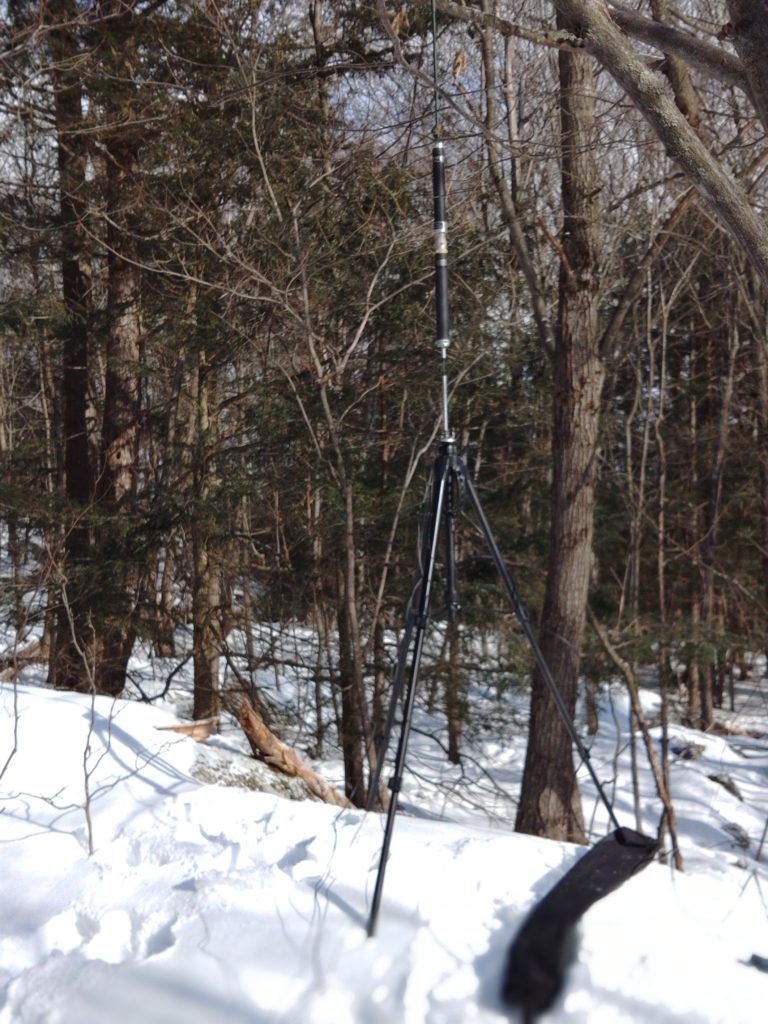
A Superantenna is set up with a 2m coil installed on a tripod. Trees and brush are visible in the background.

Superantenna and Chameleon Mil Whip 2 set up for 20m and 2m operation

In conclusion I made no contacts whatsoever and it was cold as hell, but it was a fun hike/bushwack and my winter gear held up very well against the cold. I’d like to try this again someday, but with the trail friendly 10/20/40m endfed. I also have more experimentation left to go to get my Mobilinkd TNC3+ working properly to do APRS. As a note it wasn’t nearly as difficult to deal with the Superantenna ground plane wires as I thought it might be. The main problem I had was that I’d wound them in a way that allowed them to get tangled up and deploying them was difficult. Rolling them back up wasn’t too difficult even when the sun was behind cloud cover.

Working ISS (01/23/2022)

This post is a bit of a quickie, but it covers an attempt to some of the basics about working ISS’ voice repeater and APRS digipeater. During this attempt to work ISS I wasn’t able to make any voice contacts, but I started with the following:

  • An Android phone running ISS Detector Pro
  • 5″ piece duct tape
  • Yaesu FT3DR
  • An Arrow handheld dual band 2m/70cm satellite antenna with built-in duplexer

Theory

As ISS or any satellite orbits earth in a non-geostationary orbit you’re likely to eventually have a certain number of passes over your location, depending on how the satellite is orbiting. You can use software to predict orbits, and therefore you can be ready when the satellite passes overhead. Ideally you’ll have the transponder frequencies of the satellite you’re trying to reach pre-programmed into your radio along with some doppler-shifted frequencies to try to reach the satellite as it approaches and departs. I didn’t do that, but have had decent luck without the doppler-shifted frequencies. Passes typically last minutes. What’s happening is that a lot of satellites have an uplink (ground -> space) and downlink (space-ground) frequency. Your radio must be able to transmit on one and listen to the other to make contacts. There are some cases where that’s not necessary such as working satellites with APRS digipeaters, or just receiving signals.

The attempt

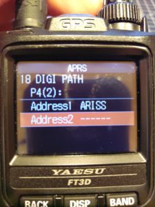
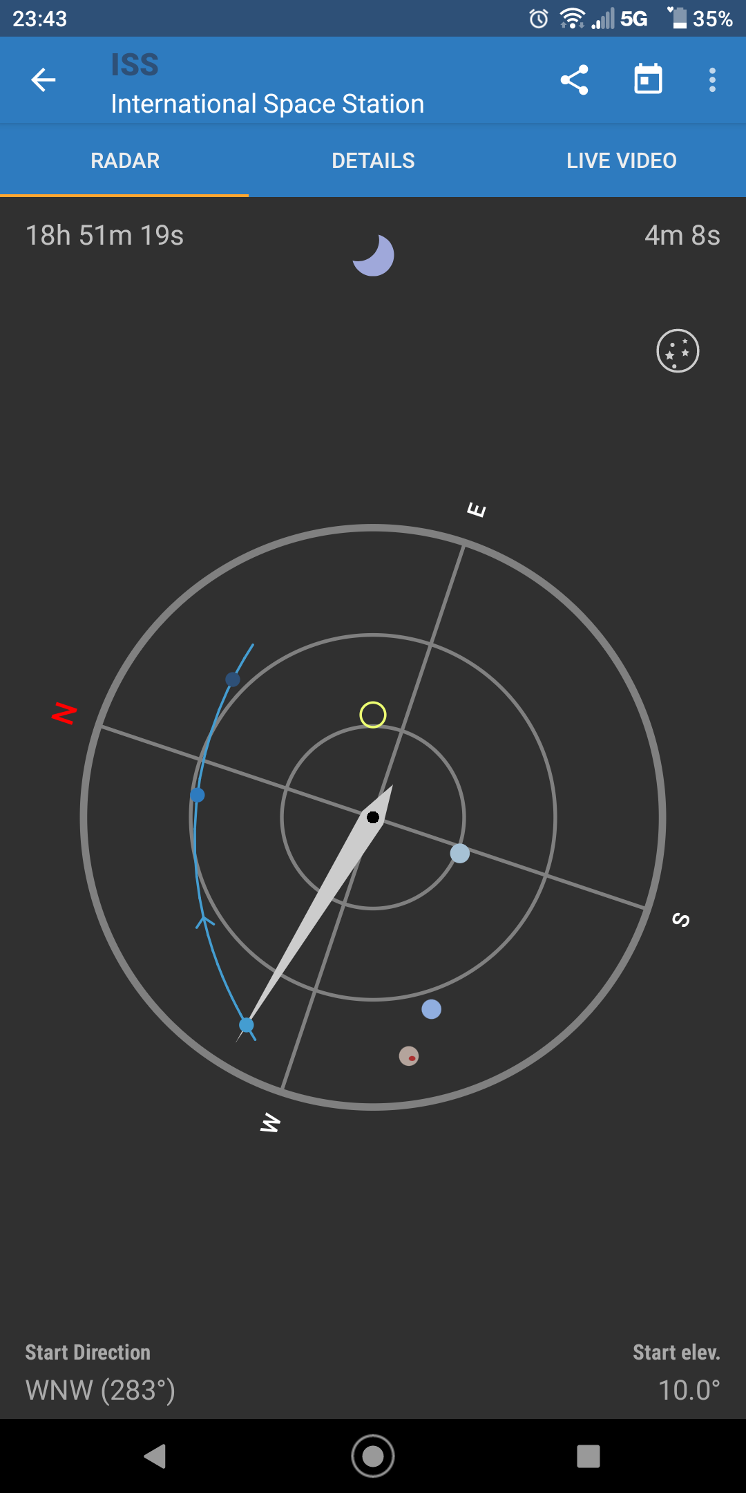
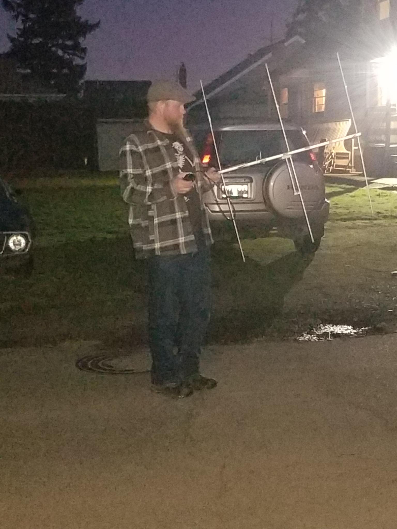
I used the ISS detector pro app to find a longer pass (this one was about 6 minutes long). Before the pass I set my antenna up, connected it to my radio, and made sure it was in working order. After that I taped the phone to the beam of the antenna between the first 2m elements where it would fit using a piece of duct tape folded in on itself. Taping the phone to the boom enables me to aim the antenna using the app (screenshot later). I also configured the frequencies for the APRS digipeater on ISS, the crew communication uplink and downlink frequencies, and the FM repeater frequencies. As a side note sometimes astronauts, who are also licensed ham radio operators, will man the radios and talk with folks on the ground. In addition to programming frequencies you need to also program your APRS radio to use the digipeater path ARISS, otherwise the digipeater won’t send your packets back down to other stations.
Yaesu FT3D radio's APRS path configured to be "ARISS".
Yaesu FT3DR digi path set to ARISS or ISS.

Now it’s time for action! There’s a very narrow window to hit the ISS, so there’s a need to be quick and prepared. I went out in the street near my house a few minutes early with a clear-ish view of the sky and aimed the antenna at the satellite using the app. A screenshot below shows what the aiming screen looks like. The yellow circle is the direction the top of your phone is pointing and that should be aligned with the satellite on its track, the blue line with dots. The center of the screen is up and the and the outer ring is down. As the satellite passed I just aimed the antenna with the aid of the phone and tried to use the repeater. I didn’t hear anyone, but was able to switch to APRS and sent a beacon. I saw that the packet I sent was digipeated by ISS! Following that I checked the ARISS page and saw my call sign! You can also check https://aprs.fi and see your location as well as the path by which your packet arrived. The first hop for my position report was the ISS.

aprs.fi screenshot showing a path via NA1SS
An aprs.fi screenshot showing a path digipeated by NA1SS before going to APRS-IS via KM6YLW-2.

Camping in the Tillamook State Forest (1/21-23/2022)

It’s been a while and this will be a big post! My partner and I were able to go camping over the weekend, and if you’ve read any of my blog posts you won’t be surprised that I took the opportunity to practice some comms and off grid operating. I wanted to work HF, do some shortwave listening, and see if I could do any UHF/VHF communications. Additionally I wanted to run off of the 100AH battery box for a couple days to see how well it held up under constant use. This is also the first camping trip I brought the speaker stand antenna mast setup on.
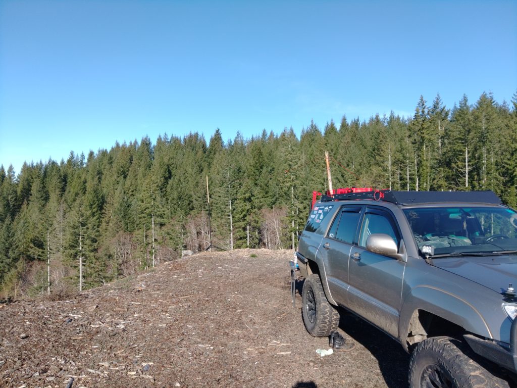
On the way out I ran APRS with the Kenwood TM-D710G and the COMET-NCG CA-2X4SR antenna that mounts on the hood of the 4Runner. I noticed that on the way out that I had APRS coverage nearly the whole way out.

The first night we arrived late so I did a bit of SWL. I mostly got Radio Havana Cuba, Radio Nikkei, a distant station broadcasting in Mandarin, and Radio New Zealand International.

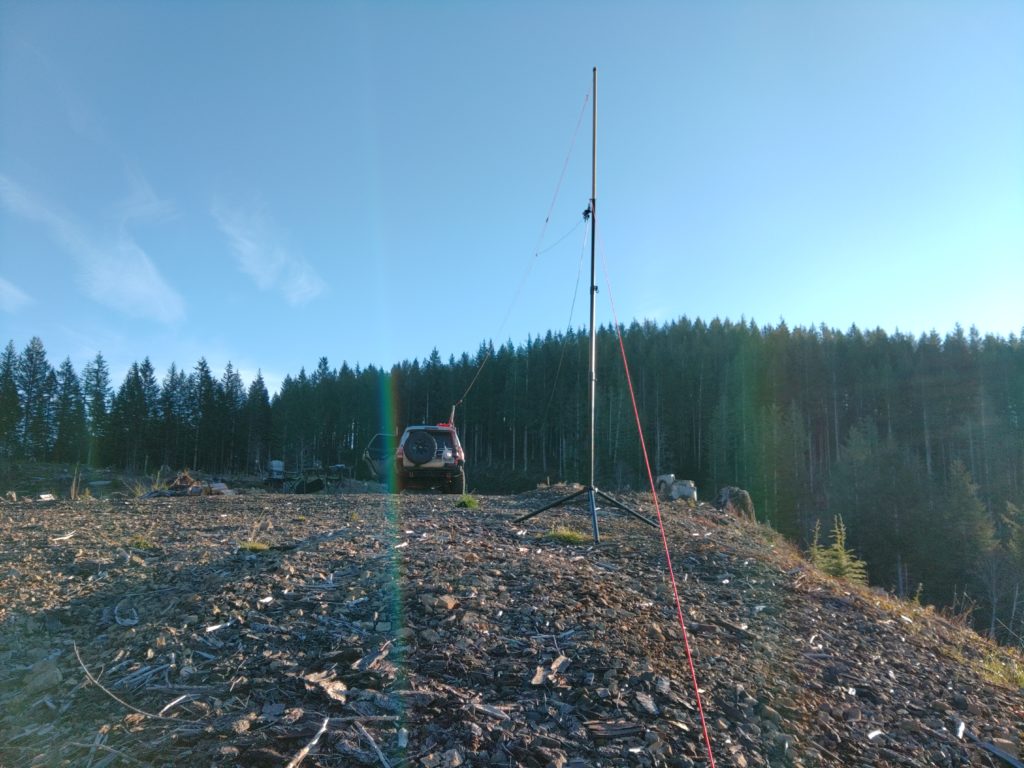
The next day I set the antenna up following a fun walk in the woods below the camp site. Most of my work on HF was done using the usual Endfedz Trail friendly 10/20/40m antenna. I strung it between the 4Runner and my portable antenna mast. I also added a 6m end fed dipole to the setup to see if I could reach Kevin, K7AJK from my camp site on the Lab599 TX-500. We had no luck. I wasn’t actually able to make any voice contacts on 20m with this setup even running at 10W, but there was a contest on the band so it was both congested and I suspect folks were running at fairly high power levels to make contacts. As you’ll be able to see from photographs I did a little hack with a stick I found to push the antenna higher off the ground on the truck side. It was especially helpful in preventing the hatch back from striking the antenna.
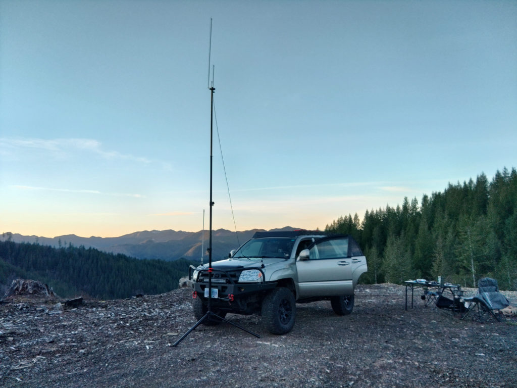
View of an antenna mast guyed to the ground and a line with an antenna running to a SUV in the background
Guyed antenna mast with two antennas added
View of an SUV with a piece of wood lashed to the roof rack holding some paracord off of the top of the vehicle.
Found piece of wood used to push the antenna higher off of the roof of the 4Runner
An antenna tied to paracord running from the upper-right corner of the photo to a mast several feet away on the edge of a hill. The transformer for the antenna is visible with feed line hanging down. Forest in the background.
The Trail Friendly Endfedz is strung along some paracord to prevent damage to the antenna if the mast blew over.

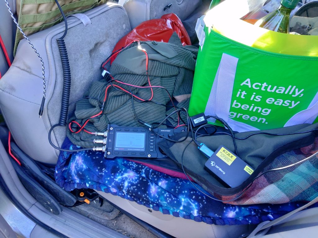
After a few hours of having no success running phone I decided to switch to packet. Moving the radio into the vehicle reduced the SWR and allowed me to run the entire setup from the 100AH battery since I had used the 4.5AH battery quite a bit for SWL already. I had also been simultaneously been running my 2m rig and APRSDroid on the tablet connected via Bluetooth to the mobile radio with a Mobilinkd TNC3+. I was able to send a number of text messages back and forth between friends using SMSGTE, which was nice given the complete lack of cell service. At this point I was still using the antenna on the truck.

A Raspberry Pi connected with a Lab599 TX-500 radio via two cables sitting in the back of a 4Runner.
Lab599 TX-500 connected to the off grid Raspberry Pi
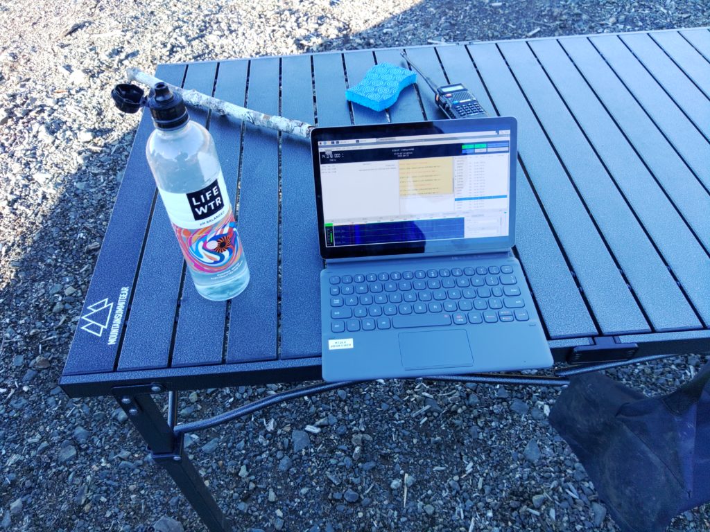
A tablet sitting on a metal camping table running the JS8Call application.
Tablet running JS8Call
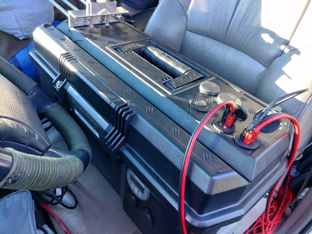
A toolbox with power connections running from it sitting in the front seat of a vehicle.
100AH battery box connected to the Kenwood TM-D710GA in the vehicle, the Lab599 TX-500, and some lighting.

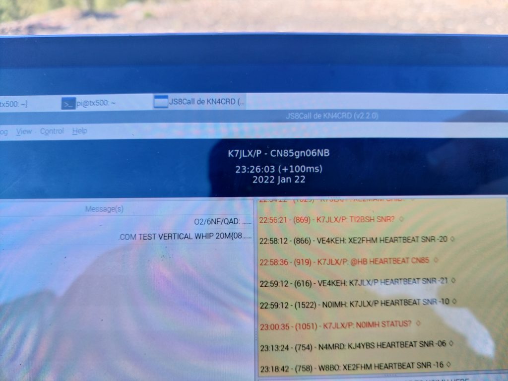
After quite some time operating on digital I decided to test some configuration changes I made to js8cli to increase the accuracy of maidenhead coordinates I was submitting to APRS-IS via Internet-connected stations running JS8Call. I had some pretty good luck as my position was accurately reported.

A photograph of the screen of a tablet showing the JS8Call application running. A callsign, timestamp, and 10-digit maidenhead coordinate are displayed prominently in the photo along with a screen showing contacts with other stations.
JS8Call screen shot showing a 5-level maidenhead position set via js8cli running an daemon mode
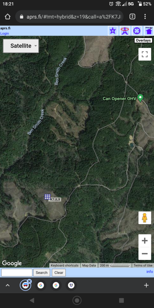
A screenshot of the website aprs.fi showing a Google satellite map with a rectangular marker for K7JLX placed in a clearing.
My position as displayed on aprs.fi

Apart from all the fun I had on HF, and walking around the forest with my HT (where I was reliably digipeated at 5w) I also figured I’d try to see if I could hit some of the repeaters in the Portland area, so I swapped the vertical antenna on the vehicle for my collapsable J-pole and speaker stand antenna mast. Much to my surprise I was actually able to get into the repeaters in the Portland area at 5w, but it was a bit sketchy as sometimes they wouldn’t key up. Apart form that I could get a bunch of APRS stations and digipeaters as well as some folks on the 2m calling frequency. I actually ended up having much better luck on 2m than on HF this time around.

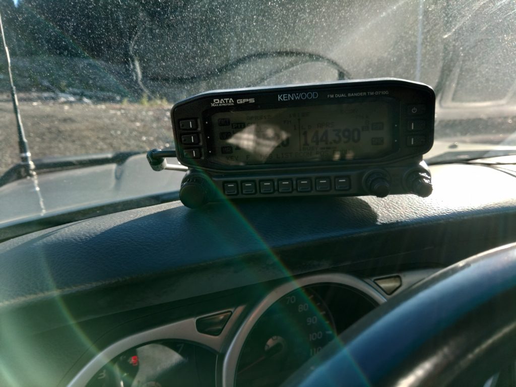
The head unit of a Kenwood TM-D710GA radio placed on the dash of a vehicle.
Kenwood TM-D710GA on the dash of the 4Runner
A 4Runner with an antenna mast tied to the front bumper and connected to the vehicle with feedline. There's a camping table and chairs to one side and in the background are trees, a valley and a mountain on the other side of the valley.
The 4Runner antenna hood antenna swapped for an elevated J-Pole on the speaker stand mast.
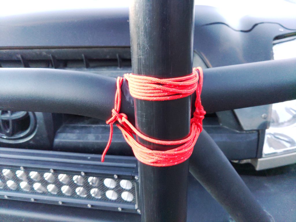
Close-up of paracord tying the the antenna mast to steel tubing on an offroading bumper.
Using paracord to lash the antenna to the bumper of the truck

As you might have noticed from the pictures above I ended up moving the antenna because winds were getting higher and I was afraid the antenna might move side-to-side on the bumper’s tubing. I ended up shifting it toward the driver’s side where I could secure it to both the tube running horizontally and to the spot where the tube split, meaning the mast wouldn’t shift from side to size because it was secured with the paracord on both axes. since the antenna mount on the vehicle uses the same connector as most of my coax and the J-pole I was able to just connect the J-pole directly to the existing cabling in the 4Runner. Easy!

For the entire trip apart from doing some SWL with the TX-599 on its 4.5AH battery away from the truck and by the fire ring I ran all the lighting and radios from the 100AH battery box. We charged the tablet, my partner’s phone, and my phone from the battery box as well. We only drew down to 96% in two days. One day had a lot of heavy radio usage as well so that’s all a good sign.


Yellow witch's butter growing from the top of a tree stump with diamond cut patterns.

Some witch’s butter we found on a stump near our camp site

Working portable from WY

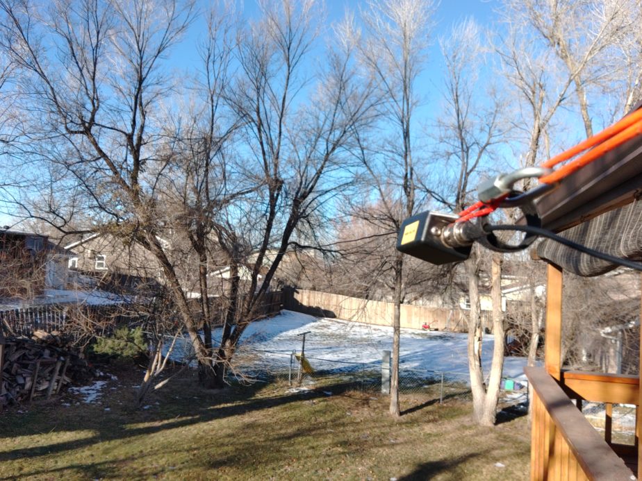
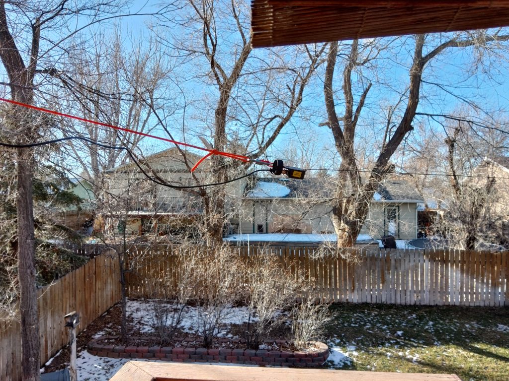
Hello all, after leaving my last post in draft for a few months and not finishing it I figured I’d move right along and write another one! I had already set up my superantenna last night to do some SWL, but because the space weather is so good I decided to set up the Par EndFedz EFT-10/20/40 antenna to do some work on 20m. For today I used the arborist’s weight to hang the far end of the antenna in a tree in the back yard and connected the transformer end to the deck. The antenna was an estimated 20′ off the ground, and was oriented diagonally SE to NW across the yard. I had intended to run the antenna north to south but was unable to because the antenna was too long to be stretched from the deck to the right tree. I ended up moving it to another tree diagonally across the yard.

I made a partial contact with a Canadian ham out of Victoria, BC that suggested the solution to someone interfering with him was to “invoke the 2nd amendment” and solve the problem with a gun. Following that gem of a first partial contact of the day I decided to get off phone at that point and start operating JS8Call on 20m.

I connected the Raspberry Pi to the battery and Lab599 TX-500 and fired it all up. One of the first things I noticed was that the system clock was wrong. After using “timedatectl status” I saw that my hardware clock was right but on boot it failed to update the system clock. At that point I did it manually (“sudo hwclock –hctosys”). Since I had connected the Pi to the wifi at the house the previous night to run updates I was able to set my tablet up in the kitchen and leave the radio outside while I operated as there wasn’t enough cable to bring the radio inside. The family was around inside and it was considerably warmer in the house than it was outside so I could make QSOs and still talk with everyone that was inside. That’s one of the nice things about using keyboards and a slower mode like JS8Call – you can still talk with people while messages are being sent and received.

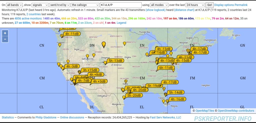
I made a few contacts but had a nice long QSO with W7SUA in AZ. Apart from that I was getting two way communications with stations over 1,800 miles away though they were generally automated requests for signal reports and locations.

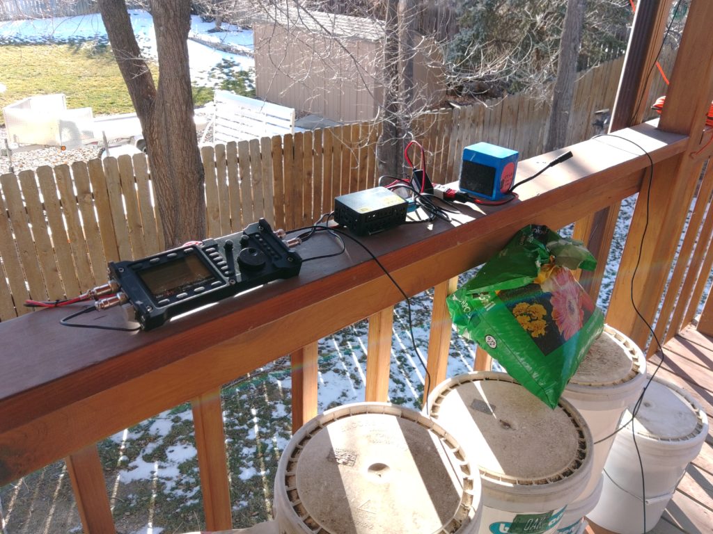
Radio, Raspberry Pi, and a 4.5Ah Bioenno battery pack connected on a deck railing.
Radio set up with Rasbperry Pi connected.
Samsung Android tablet set up on a table showing a VNC session that's running JS8Call.
Tablet in the kitchen operating the radio while it’s outside.
Side view of the transformer end of the EFHW antenna connected to the deck with orange paracord and a coax cable.
Transformer end of trail-friend EFHW attached to the deck
Long view of the EFHW antenna connecting to a tree across a back yard.
View of the antenna running from the deck to the tree.
Image of https://pskreporter.info showing contacts from my station to others througout the US.
pskreporter.info screenshot showing stations that could hear mine throughout the day.

Bench testing 100Ah battery box improvements

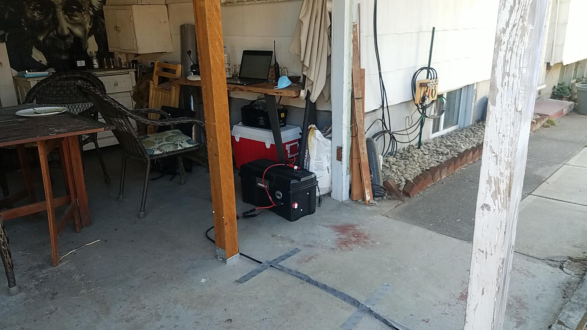
Battery box sitting on a concret slab with wires running from it.
Battery box with solar power and a 90W USB charger connected via a PWRNode
Zoomed out view of the battery box with a wire running to it from the right that's taped down, a laptop on a bench near the battery box with wires running into it from the battery box.
A wider view of the work area with the solar cable taped to the ground and the laptop on a workbench

With a potential COVID-19 exposure I decided to work outside in order keep my housemates’ exposure as low as possible. This afforded me the perfect opportunity to test running a high performance laptop from my batery bank and on solar power. I wanted to bench test integrating a West Mountain Radio Epic PWRGate into the existing battery box that had been intentionally designed without and integrated charger. The first and second days of the test with good and poor sunlight respectively went well. The solar panels were holding the battery up and by the time I was done working the battery was fully charged. It is worth noting that earlier in the morning the laptop was running on the battery, but as the sun came up the battery began recharging in both cases. Of course the battery charged more slowly and sometimes went into a discharging state on the cloudy day but ultiately all the power drawn from the battery was replentished.

Two powerpole ports populated with power cables on the power box's side.
The added solar (left) and UPS (right) powerpole connectors
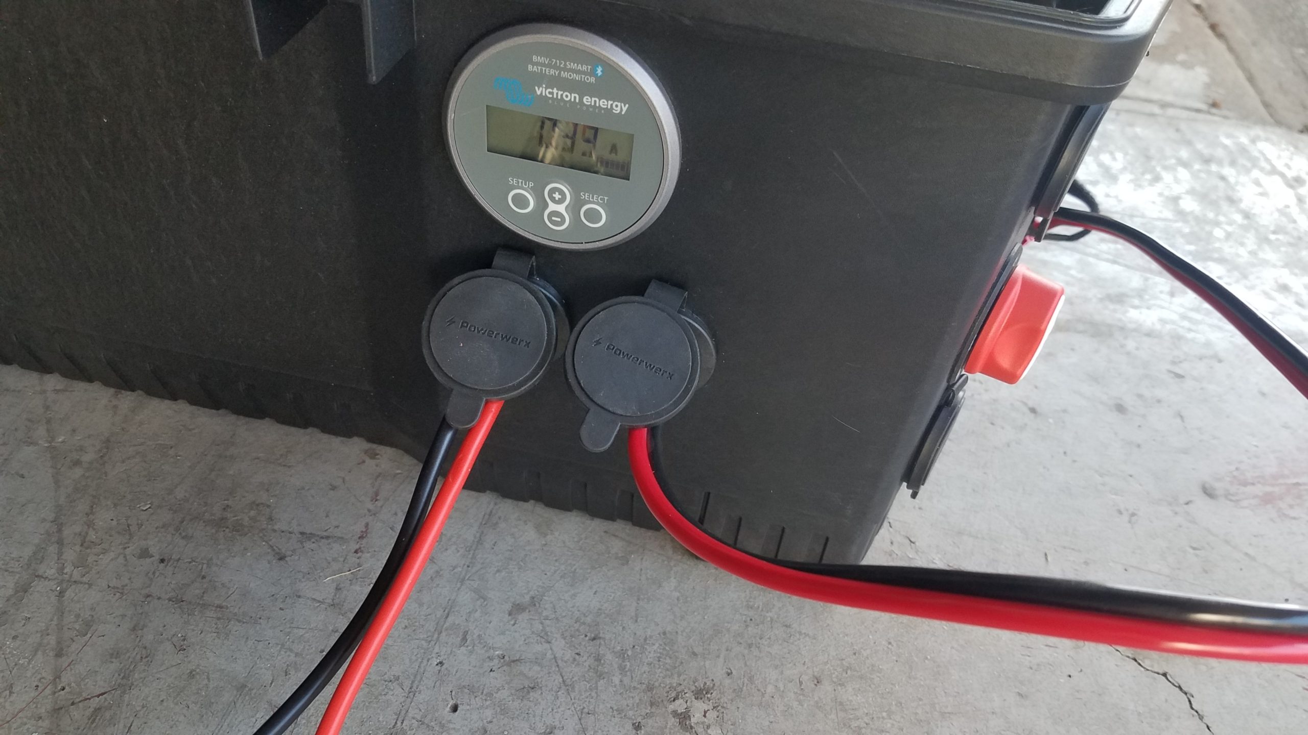
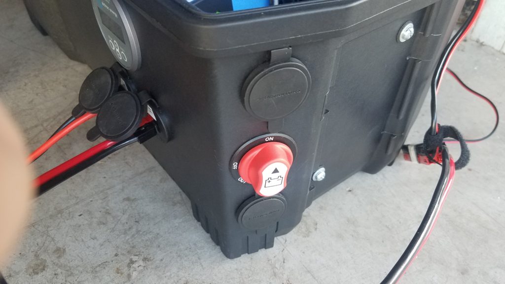
View of closed powerpole ports, two populated powerpole ports, and a red disconnect switch as seen from the corner of the battery box.
The existing 30A charging port (top), added disconnect swtich for the charger (middle), and added DC in port (bottom)

I added three new Powerpole ports to support the installation of a West Mountain Radio Epic PWRGate for use as a multisource battery charger and to allow one port on the battery box to function as a UPS, one as a DC charging input from a vehicle or other 12v power supply, and a solar panel input that can work with lower voltage (<30V) solar panels. I also added a charger disconnect switch that prevents the charger from acting as a parasitic load when it’s not in use. The specific disconnect switch I added allows the red rotary part of the swtich to be removed n the event you want to make sure the charger isn’t connected to the battery by mistake.

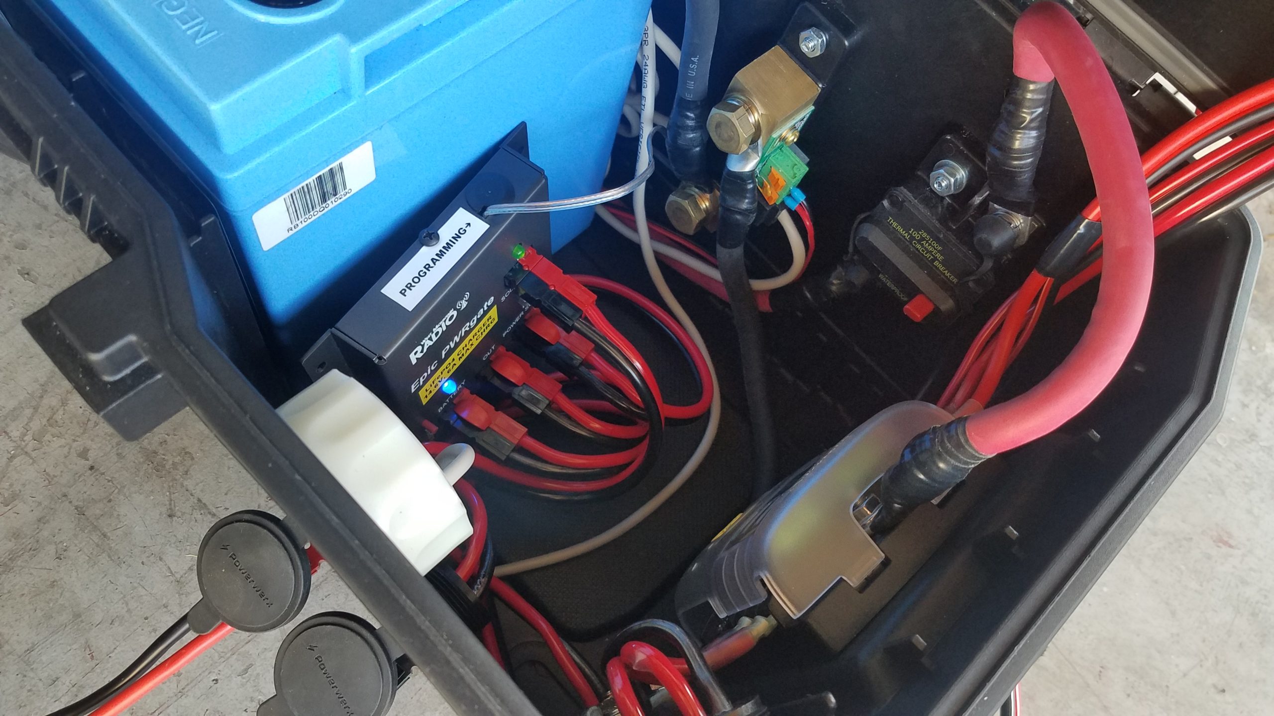
Open battery box revealing connections between internal components including the Epic PWRGate.
Opened battery box with the Epic PWRGate connected for testing

The Epic PWRGate connects to the ports with 10GA stranded copper wire to support 30 amp loads. The “battery” port on the PWRGate is connected to the battery via the DC disconnect switch and the DC subpanel. The leg of the circuit that connects the battery to the charger is also fused with a 30A fuse to allow it to operate a full power radio via the UPS port. The Epic PWRGate will charge a battery with a max current of 10A. I also added an optional temperature probe connected to the positive battery lug that will cut the charger off when the battery gets too cold or warm to prevent harm to the battery. The temperature parameters are configurable using the USB port. The appropriate USB cable, USB C, and USB A OTG cable adapters are included to connect a device with a serial terminal emulator installed.

Block diagram of 100Ah battery box

This updated simplified build diagram for the 100Ah battery box includes the modifications that were being bench tested and will likely remain as a permanent addition to the system for charging from a vehicle or charging from a lower voltage (<30v) portable solar panel.

As a side note an added advantage of including a charger like the Epic PWRGate to this setup is that it can be re-configured to charge another battery, even of a different chemistry from the 100Ah LiFePO4 battery. You can charge a smaller battery or even charge a lead acid battery from it as well. This will require changing jumpers if you’re not programming the unit with a USB port, but I prefer programming it with a USB port as I get a better degree of control over the settings such as charge current than the onboard jumpers provide. It will also require swapping the battery and DC ports. The battery should be connected to the DC port and the DC port should be connected to the battery being charged. In the event the charger is re-configured I also include the custom LiFePO4 battery settings for my Relion RB100 that the kit is designed around so they can be restored on the charger without requiring memorization.

Solar panel suspended from paracord in the sun.
Suspended foldable solar panel

I also ended up having shading issues in the space that was available to set up the solar panels so I used the built-in eyelets and some paracord to suspend the panel in the sun to avoid shading on the ground. I was also able to slide the panel laterally on one piece of cord running left to right (east to west) near the water tank pictured. The other piece of paracord goes through both of the eyelets and forms a tiangle whose point is a knot and the single line of paracord runs back to a single anchor point from the triangle, and is pointed south. You can slide the panel side to side on the paracord running right to left (east to west) as the sun’s position in the sky changes. Getting the panel off the ground was extremely helpful because it got the system out of shadows cast accross the ground most of the day, and also required less maintenance as shadows tracked across the ground and threatened to partially or fully shade the solar panels. Instead the shadows were cast under the suspended panel.

The 100W folding panel was able to charge both a 19″ Macbook Pro connected to a 90W USB C car charger and a phone the an entire work day. This worked well on a bright day and on a cloudy day using this new configuration. I leverage MC4 connectors for the 100W panel to harden the connections against rain and dust. They’re adapted to Anderson Powerpole connectors for connection to the battery box using a pigtail I store in a zippered pouch on the back of the folding panel along with rolled lengths of wire with MC4 connectors attached.

This is an update to this post about building the battery box.