Hello everyone! Today I wanted to post about a topic that is pretty important if you have an interest in off grid, grid down, or emergency communications: estimating power consumption for your equipment. This post is in part inspired by a topic I chose for the Portland Neighborhood Emergency Team chat net. Shortly after I chose this topic I got an e-mail from Kevin, N6KVN asking for some advice for setting up a portable field station, and so I figured I’d write a more detailed post about my methodology and way of thinking about operating a ham radio station when grid power isn’t available from a preparation or pre-planning standpoint.
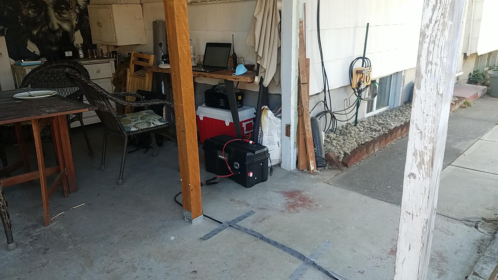
My basic test setup consists of three components. I have a power source of some kind. This could be a battery or a wall-connected power supply. The next component is a power meter connected between the load(s) and the battery. This component actually does the work of measuring power consumption. The final component of the test setup are the loads you wish to test. It’s important to make sure all the components in the setup are rated for the amount of current you expect to draw during testing. You can usually find that in the specifications of each individual component. You add those up and make sure your meter is rated for that much current and that your power supply can supply all of the required current. All the wiring in between should also be properly rated for that amount of current.
Example lighting current draw test
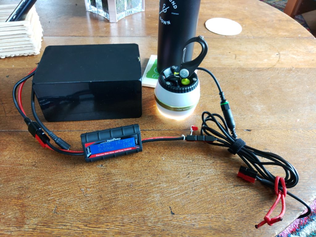
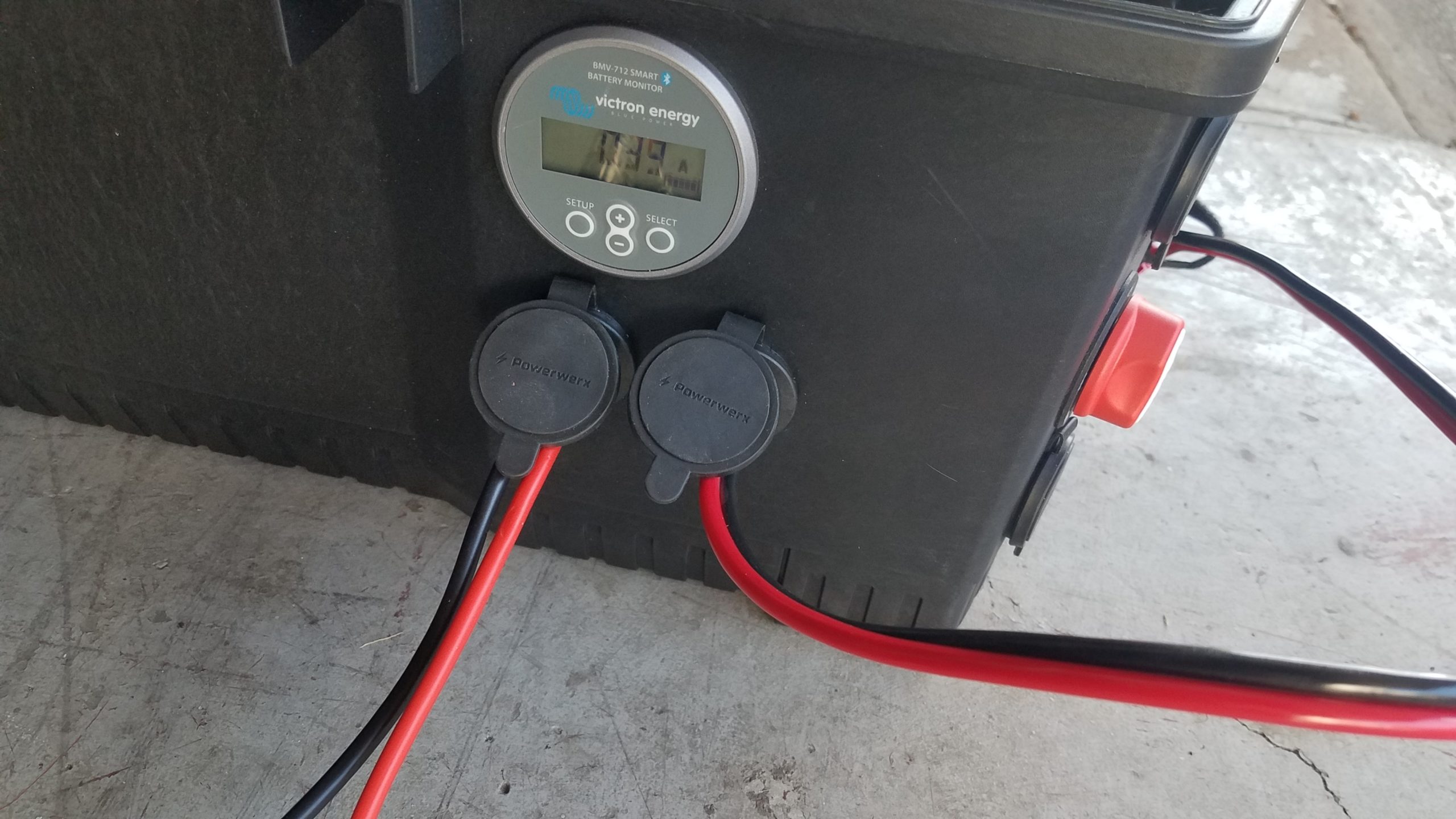
In this example I demonstrate testing a lighting device that runs on 12V and explain my methodology for hooking everything up and how I use back-of-the-napkin math to estimate power usage and requirements. In the above photo we have all three of our components for this specific test – a power source which is a battery in this case, the Powerwerx inline DC power meter, and load which is an LED lamp whose power usage I want to characterize. The Powerwerx inline meter supports a lot of measurements but in this post I’m going to mostly focus on current drawn and Ah, or amps per hour.
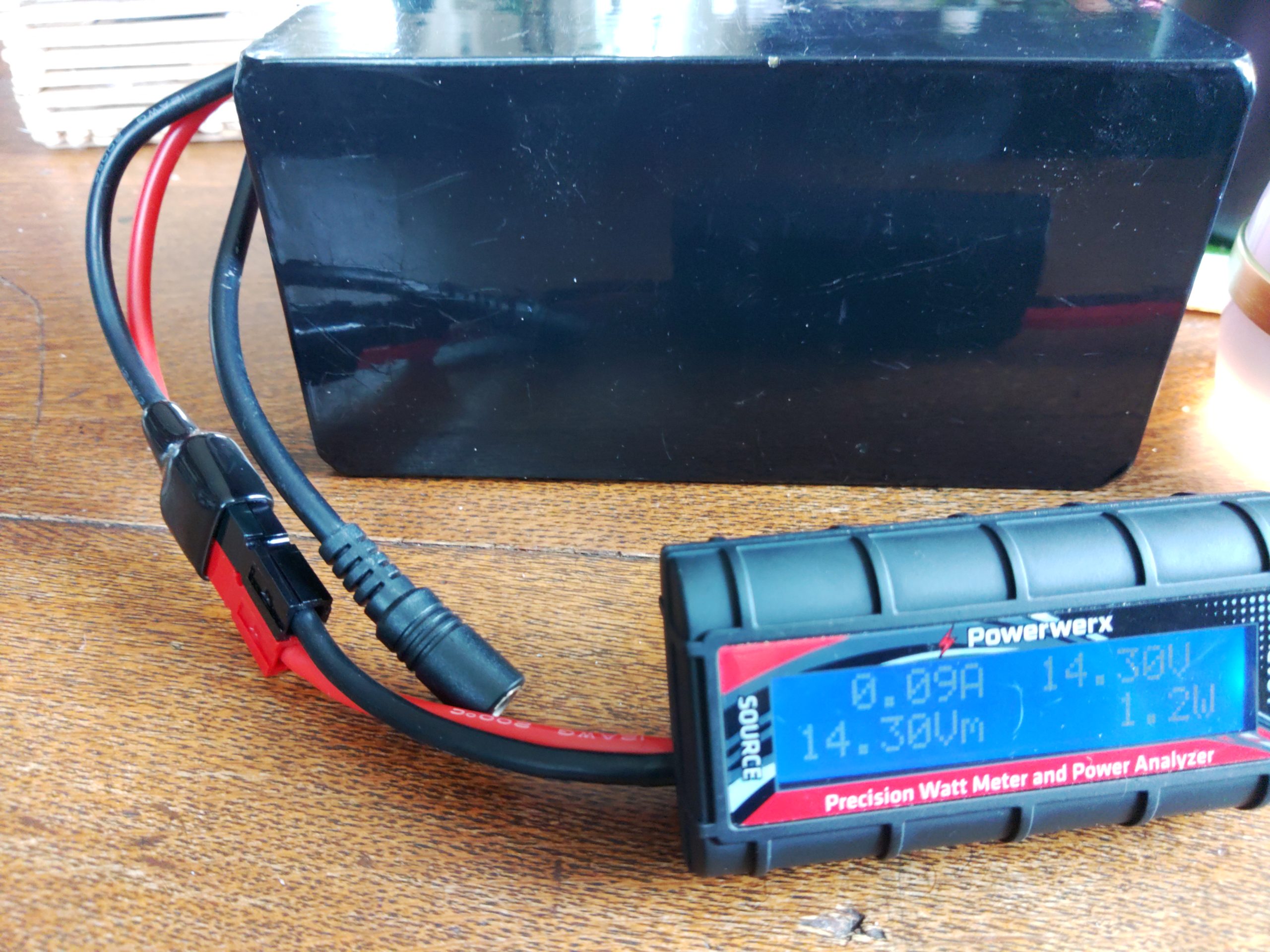
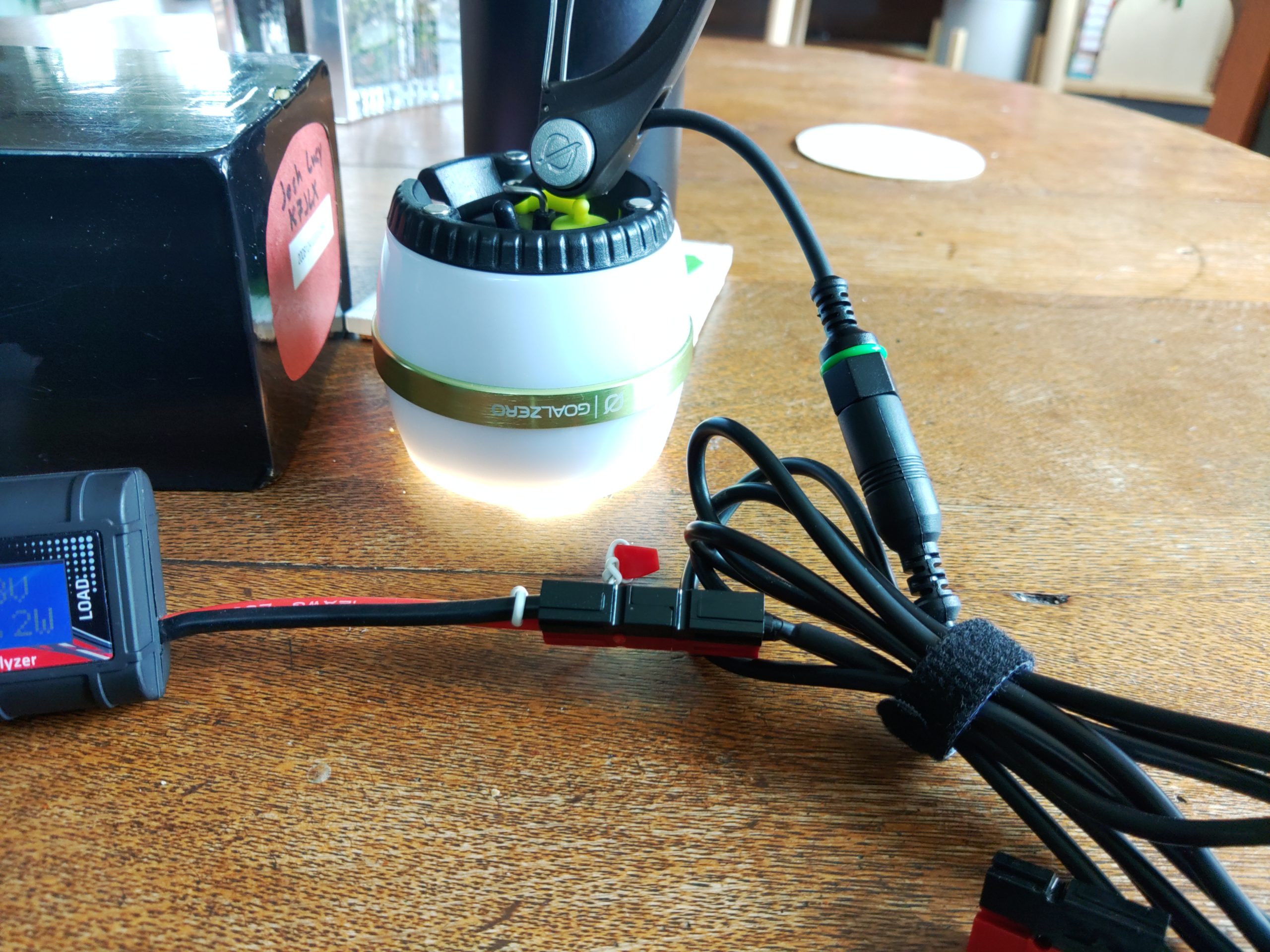
I started by connecting the power source to the “source” side of the power meter and then connected the load I wanted to test to the “load” side of the power meter. The images above show the light on but I will usually measure power with all the loads turned off to see if they draw current in the “off” position. It’s pretty common for devices to take a small amount of power even while off. This is called a parasitic load. The specific LED lamps I wanted to test have three settings: off, low, and high. I tested off and my power meter registered no current consumption. That’s probably because these lights have a hard off switch.
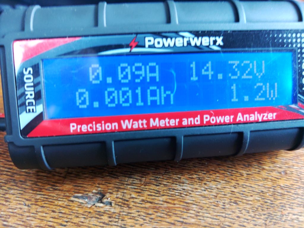
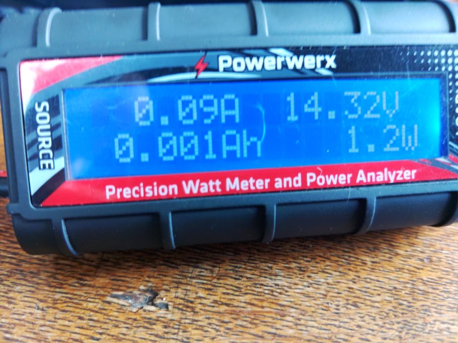
As you can see here this light draws 0.09A in the “low” position. If we were to run this device for 1 hour it would take 0.09Ah (amps per hour). You might have also noticed that there’s a measurement reading 0.001Ah. For this specific meter that means we’ve used 0.001Ah since the meter was connected to a load. There will be more on this measurement later.
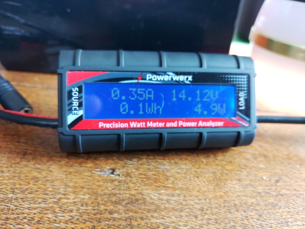
With the LED lamp in the “high” position it’s drawing 0.35A of power. With the information gathered so far I can estimate how much power I’ll need if I want to run this light for a certain amount of time, and I can figure out how much power I can expect it to take while it’s running. If we use the Ah reading I mentioned earlier we can also understand how much battery capacity we’ve used since the last time the meter was restarted. Let’s start with that since I mentioned it.
To determine how much battery we’ve used as a percentage I’d use the following formulas:
battery capacity used as percentage = battery capacity / battery consumed
battery remaining as percentage = 100% – battery capacity used percentage
For a theoretical battery with 20AH of a capacity and 2Ah consumed the formula looks like:
20AH / 2Ah = 10% capacity used
100% – 10%= 90% capacity remaining
Now let’s add time to the mix. I’m going to use a Yaesu FTM-100D radio as an example of thinking about how much power it will use based on the specifications from the manual. According to its specifications when it’s receiving only it’ll draw 0.5A. The max power it will draw when transmitting 50W on 2m is 11A. Using this information let’s figure out how much battery we’d need to operate this radio some percentage of the time for 8 hours. For the purposes of this post we’ll call the amount of time we’re transmitting our duty cycle. We’ll assume we’ll be transmitting at 50W for 10% of the time that the radio is powered on. The formula will look like this:
Ah used = current * hours * duty cycle
While the radio is receiving only during an 8 hour operating period we’ll use 3.6Ah of battery capacity:
0.5A * 8h * .90 (90% receiving time) = 3.6 Ah capacity used
Now we should compute power usage when transmitting at 50W:
11A * 8h * .10 (10% transmitting time) = 8.8 Ah capacity used
Total power consumption over 8 hours for the radio:
3.6Ah (RX only) + 8.8Ah (TX at 50W) = 12.4Ah
When we add them up we need at least 12.4 AH of battery capacity to run that radio for 8 hours while transmitting 10% of the time. If you want to run the radio for 16 hours transmitting 10% of the time you’d either need to be able to re-charge that battery to replace the discharged power before the battery gets too low or have a battery large enough to run the radio for 16 hours, meaning you had at least 24.8 AH of battery capacity. There’s also a way to cheat on battery capacity. If you can reliably charge your battery as you run your radio from a source like a solar panel you can replace current that’s drawn down by your loads. In that case you’d just subtract the current you’re able to supply from your charging source from the load. If you end up with 0 or a negative amount of current draw you’re able to power your radio without discharging the battery.
Figuring out how much power you use as you go
This section can apply to both bench testing and operating in “the wild”. This details how you’d use any power meter that’s capable of measuring cumulative power use while you’re running loads. The Powerwerx meter I mentioned earlier and the BuddiPole PowerMini have this capability. If you connect one of these power meters inline with your setup as you operate and run loads it will add the cumulative power drawn. This can be useful when you want to understand how much power you’ve drawn down on a battery. As I write this before the 4/3/2022 Portland Neighborhood Emergency Team chat net and NET net I plan to operate on battery with lighting during the net and record my power usage here later, but the thing I do is the following for both bench testing and off grid measurements:
- Connect my power meter between the power source and load as described above
- Perform whatever activities I would normally perform
- When done I check the consumed Ah on the meter to get my battery capacity used
- Calculate battery percentage used
Formula for calculating battery capacity used:
battery capacity used / battery capacity = percentage capacity used
For an example with a 20AH battery and 15Ah of capacity used during some activity I would have 25% capacity remaining on the battery. I can use this formula in the lab to estimate how much power I’ll need in the field later, or understand how close I am to drawing my battery down in the field:
15Ah / 20AH = 75% used battery capacity
100% – 75% = 25% remaining battery capacity
Adding it all up
When you perform this kind of analysis on devices you expect to run off of battery in the field you can begin adding up all your field components and understanding what your power requirements will be. If you know your lighting will take 2Ah to run for a few hours at night and 12 hours of radio operation might cost 13.2Ah you can say your station will take 15.2Ah to operate for 12 hours. As you add more devices such as phone chargers, laptops, etc. your power requirements will change. You can also use this methodology to reduce power consumption. For example if running your radio at 5W is sufficient to achieve your communication goals you could save a lot of power, requiring a smaller battery, or less recharging capacity. You could also achieve similar results by having fewer devices or keeping your radio transmissions more brief (decreasing your duty cycle). Comparing the sums of power consumption between different setups can also help you inform either your expectations of how to operate or what is possible with the setup you have. It can also help you right-size a battery or recharging system for your specific uses.
A real-world example
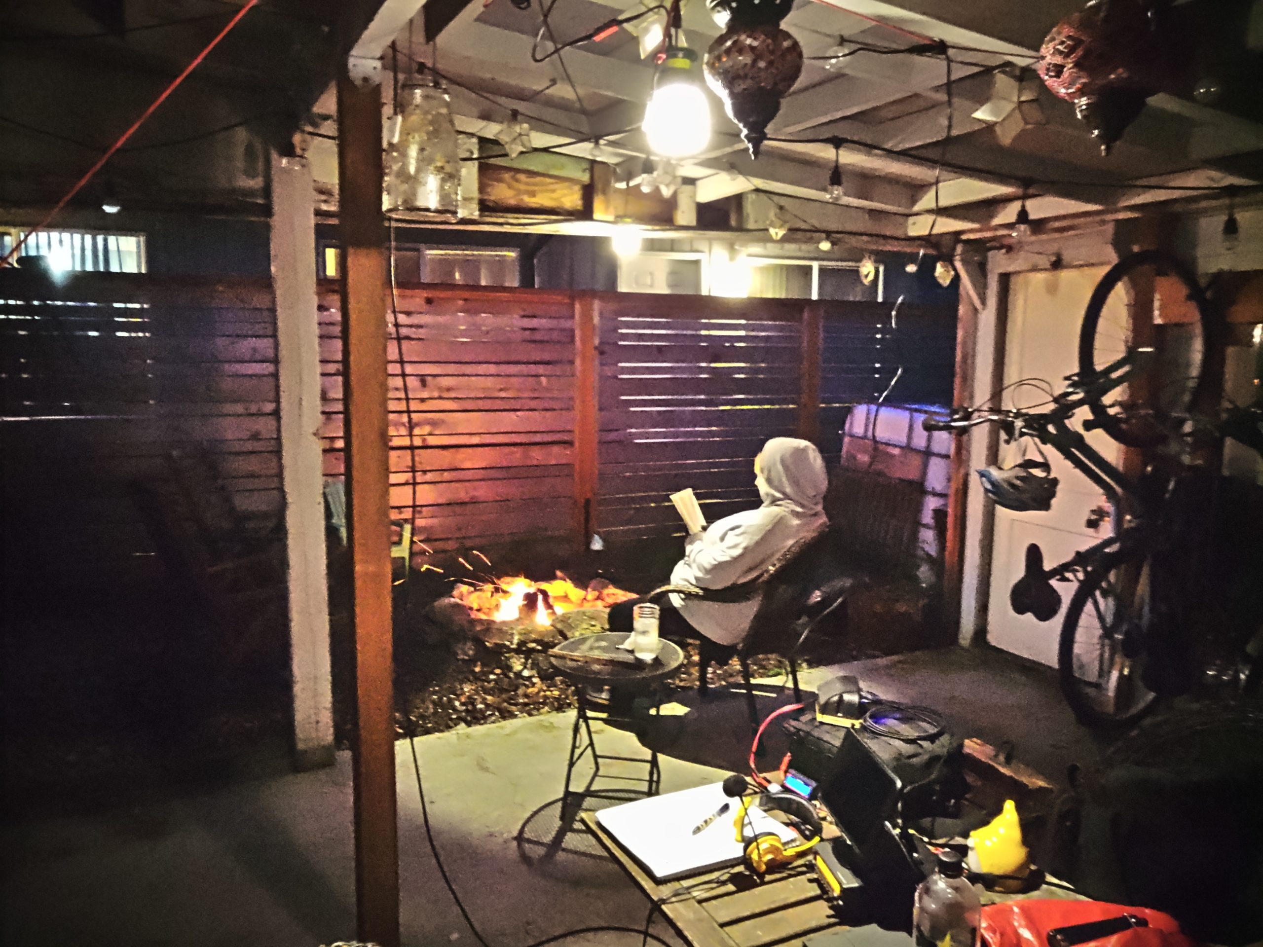
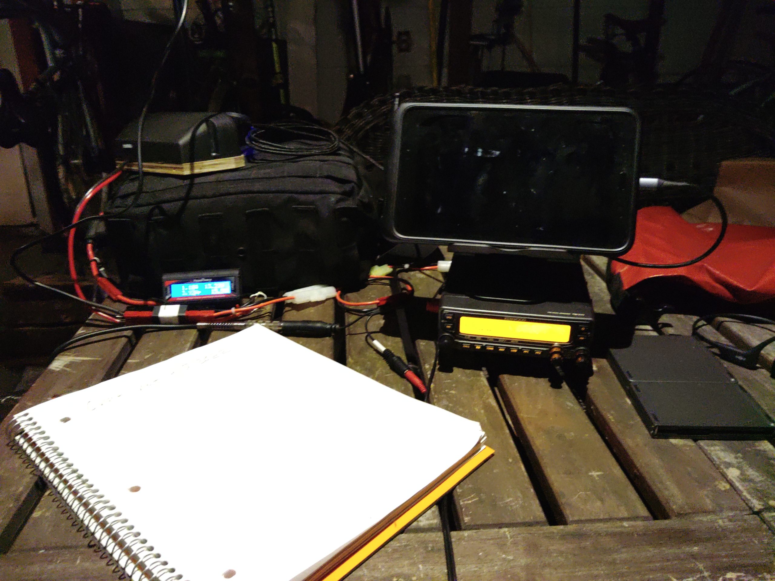
I wanted to add an update with another example of operating the radio in reasonable conditions doing a specific task that isn’t entirely theoretical, or just on-the-bench testing. Tonight I was net control for the Portland Neighborhood Emergency Team chat net, and I also participated in the Portland NET net as well. For most of the nets I was running two LED lights and I topped the last 25% of my tablet’s power off. I ran my Kenwood TM-V71A at 5w which drew about 3A when transmitting and 0.55A receiving. Both of the LED lights were set on low and consumed 0.1A apiece. The charger’s power usage varied depending on the part of the charging cycle the tablet was in, but at the end of 3 hours of running the radio, and about 2 hours of running both lights I used a total of 3.42AH of battery capacity. The battery I was using has a rated capacity of 40AH, so I used about 8.6% of its capacity (3.42AH used / 40AH of battery capacity = 0.086) doing both nets and listening on the first net’s frequency for an hour before it began. The first net that I was transmitting more on used the majority of the capacity, about 2.3AH. During the second net I only used about 1.1AH because I spent the vast majority of it listening as we ran lights and the tablet charger.
Tying it all together
By the end of this blog post I hope you came away with a good understanding of how I approach understanding and estimating my power usage and right-sizing my equipment for specific uses. This approach also helps inform how I operate when I don’t expect to have reliable power or when my situation changes and I’m not able to recharge batteries, etc. It can also show you how big of a difference it can make when you transmit less or when you add or drop devices from your setup.
This pattern can potentially be applied to other equipment like medical devices that can be run on battery. I’ve used the same method to profile my partner’s CPAP machine’s power consumption with various settings. I’ve been able to determine what sort of battery and charging system that will be required to keep it running when grid power fails or is unavailable (hint: turning off the humidifier and tube heater really saves a lot of power).
Notes after the fact
On the advice of Kevin, N6KVN I’m going to add a note about batteries. While this bit of the post is a bit out of scope it’s important to touch of the strengths and limitations of various battery technologies. Some batteries can be damaged by discharging them to 50% and others can be discharged to 20% or possibly lower before damage occurs. It’s important to understand the characteristics of the equipment you’re running. If you’ve read other posts of mine you’ll notice that I field a lot of LiFePO4 batteries. One of the reasons (apart from weight and other safety factors) that I tend to use them is because they can be discharged to a depth of 20% of remaining capacity before they’re permanently damaged. Most common lead-acid battery tech (think car batteries) can only be discharged to 50% before permanent damage to the cells occurs, but they are much cheaper than lithium batteries. Comparisons of various battery types is an entire post of its own, but these things are worth mentioning as you size your system and plan for the amount of energy you expect to discharge or plan to use. As an example my 100AH battery really has a usable capacity of 80AH because if I were to discharge the battery to 20%, or 20AH it would cause permanent damage to the battery (100AH capacity * 20% limit = 20AH, 100AH capacity – 20AH limit = 80AH of discharge before damage). This information should be listed by the battery manufacturer. If it’s not included I’d recommend reaching out to their support team.
